PIR Motion Sensor Hookup Guide
 jimblom
 Introduction
Passive infrared (PIR) sensors are motion-detecting devices used in security systems across the world -- even though you may not see them, they probably see you!
Using the PIR sensor is simple: power it up, connect a pull-up resistor to the open-collector signal pin, and watch for it to go low. The PIR can sense abrupt changes in scenery as far as 10 feet (~3m) away. Once your microcontroller is sensing movement, it can trigger a buzzer, text message, tweet, or a klaxon.
Suggested Materials
This tutorial serves as a quick primer on PIR motion sensor and demonstrates how to hook them up and use them. Beyond the sensor itself, the following materials are recommended:
Arduino Uno -- We'll be using a digital pin on the Arduino to read the state of the PIR sensor's signal output. Any Arduino-compatible development platform -- be it a RedBoard, Pro or Pro Mini -- can substitute.
Jumper Wires -- The PIR sensor is terminated with a 3-pin JST cable one of the easier ways to connect this to an Arduino is to plug a few jumper cables into the connector and run them straight to an Arduino.

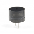

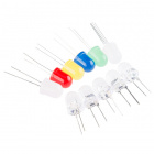
Beyond those two items, you may want to add a buzzer or large LED to make range testing of the PIR sensor more convenient.
Suggested Reading
PIR sensors are a great entry-level component for beginners, but there are still a few basic electronics concepts you should be familiar with. If any of these tutorial titles sound foreign to you, consider skimming through that content first.
Pull-up Resistors
Light
What is an Arduino?
Resistors
PIR Motion Sensor Overview
At their most fundamental level, PIR sensor's are infrared-sensitive light detectors. By monitoring light in the infrared spectrum, PIR sensors can sense subtle changes in temperature across the area they're viewing. When a human or some other object comes into the PIR's field-of-view, the radiation pattern changes, and the PIR interprets that change as movement.
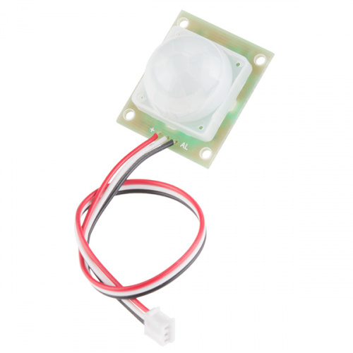
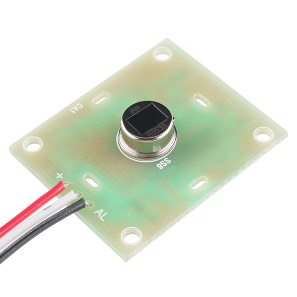
That white cap dominating most of the top side of the PIR assembly is a lense, which helps focus the PIR sensor's field-of-view. The actual PIR sensor is hiding under that lense:
The back side of the assembly sports amplifiers, voltage regulators and other supporting circuitry to help drive the PIR. All that's left for us to connect is three pins: power, ground, and the output signal.
Power and Signal Pins
The top side of the PIR assembly includes two labels: "+" and "AL". The "AL" pin is the alarm pin -- don't let the black wire fool you, this isn't ground! "+" is the PIR sensor's power supply input, leaving the unlabeled middle pin, with the white wire, as ground.
| Wire Color | Pin | Notes |
|---|---|---|
| Red | Power | 5V[1] to 12V |
| White | Ground | |
| Black | Alarm | Open-collector output – active low |
The PIR sensor should be powered with at least 5V, but it can work with voltages as high as 12V. Fortunately, even if a PIR is powered higher than 5V, the alarm pin can still connect directly to an input pin because it is designed as an open-collector.
When the PIR senses activity in it's viewing area, it pulls the alarm pin low. But when the sensor is inactive, the pin is basically floating. To avoid any false-positives, the alarm output should be pulled high to 5V. Most microcontroller's have internal pull-up resistors on their I/O pins, which can easily accomplish that task. You can also pull it high to 3.3V if you are using it with a 3.3V system (e.g. 3.3V Arduino or Raspberry Pi).
Bypass Jumper - If you only have 5V available (e.g. you are pulling 5V from the Arduino's USB, Particle Photon's USB, or Raspberry Pi), you could bypass the voltage regulator by adding a jumper between the L78L05's VIN and VOUT pins. Just make sure that the voltage is regulated and clean. The images below highlightt the pins to bypass the voltage regulator. The pins of the SMD voltage regulator are small so you could also solder wire directly to the "+" pin as well.
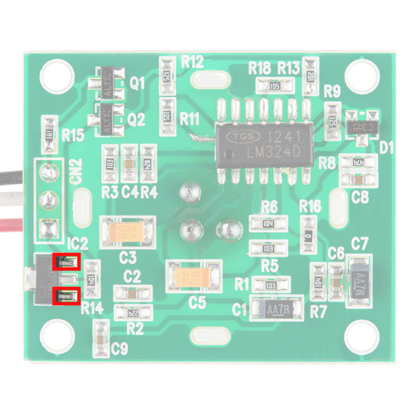 |
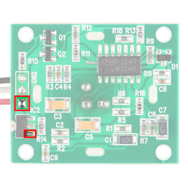 |
| VIN and VOUT Pins Highlighted | "+" and VOUT Pins Highlighted |
Example Circuit
The circuit for this example is about as simple as it gets. Grab three jumper wires and insert them into the JST connector. It gets a little tight, but they should all be able to fit in there.
Connect the power (red) and ground (white) wires up to 5V [1] and GND respectively. Then connect the black alarm wire to Arduino pin 2.
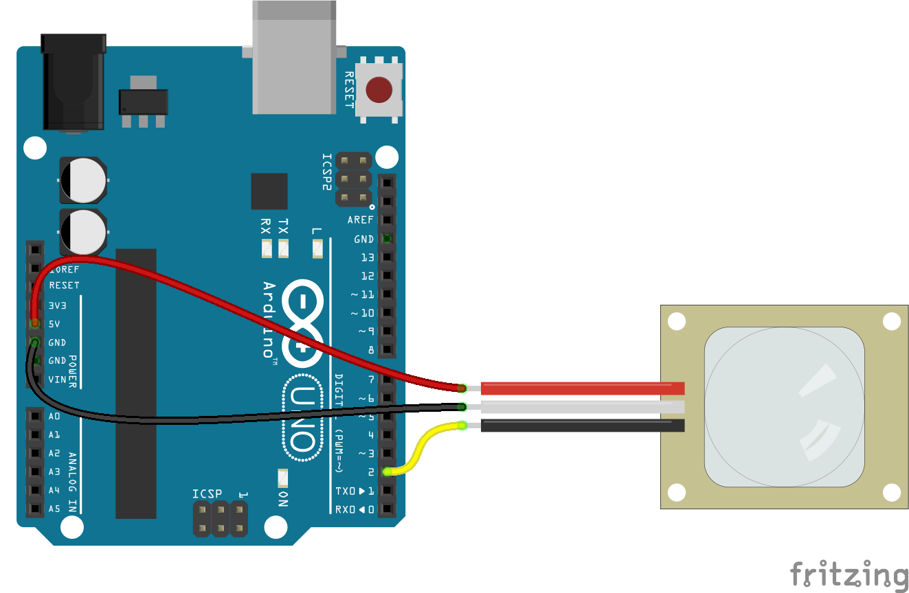
We'll use the internal pull-up resistor on D2 to complete the circuit. Whenever the sensor is inactive, the pin should read high. When motion is detected, the sensor will pull D2 low.
Example Code
Here is a simple Arduino example based on the circuit above. Copy and paste this into your Arduino IDE, then upload!
language:c
/******************************************************************************
PIR_Motion_Detector_Example.ino
Example sketch for SparkFun's PIR Motion Detector
  (https://www.sparkfun.com/products/13285)
Jim Lindblom @ SparkFun Electronics
May 2, 2016

The PIR motion sensor has a three-pin JST connector terminating it. Connect
the wire colors like this:
- Black: D2 - signal output (pulled up internally)
- White: GND
- Red: 5V

Connect an LED to pin 13 (if your Arduino doesn't already have an LED there).

Whenever the PIR sensor detects movement, it'll write the alarm pin LOW.

Development environment specifics:
Arduino 1.6.7
******************************************************************************/
const int MOTION_PIN = 2; // Pin connected to motion detector
const int LED_PIN = 13; // LED pin - active-high

void setup()
{
  Serial.begin(9600);
  // The PIR sensor's output signal is an open-collector,
  // so a pull-up resistor is required:
  pinMode(MOTION_PIN, INPUT_PULLUP);
  pinMode(LED_PIN, OUTPUT);
}

void loop()
{
  int proximity = digitalRead(MOTION_PIN);
  if (proximity == LOW) // If the sensor's output goes low, motion is detected
  {
    digitalWrite(LED_PIN, HIGH);
    Serial.println("Motion detected!");
  }
  else
  {
    digitalWrite(LED_PIN, LOW);
  }
}
After uploading, have a look at your Arduino's pin 13 LED. You can also open your serial monitor, and set the baud rate to 9600 bps.
The PIR sensor requires approximately 15 seconds of motion-free activity, while it gets a "snapshot" of it's viewing area. Try not to move until the pin 13 LED turns off, then wave your hands, jump in the air, go crazy!
Resources and Going Further
For more information on the PIR sensor, the PIR motion sensor datasheet may provide some insight.
Now that you've got your Arduino hooked up to a PIR sensor what motion-detecting project are you going to create? Need some inspiration? Check out some of these related tutorials using the PIR motion sensor:
Photon Remote Water Level Sensor
SparkFun Inventor's Kit for Photon Experiment Guide
Or check out these tutorials using sensors to detect motion or movement.