micro:bit Breakout Board Hookup Guide
 Shawn Hymel, Ell C
 Introduction
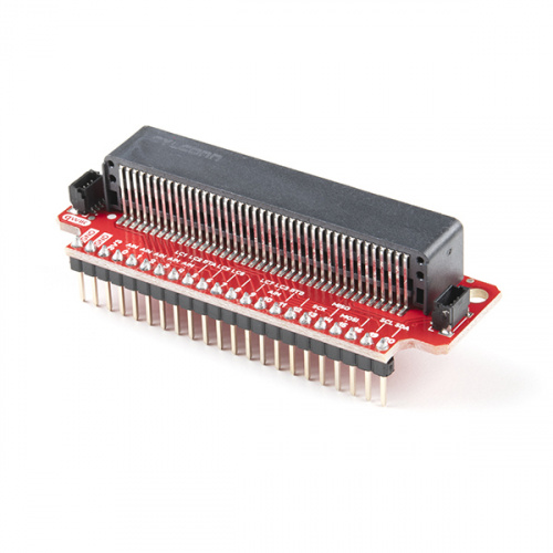
The micro:bit, by itself, offers a vast array of possibilities and potential projects, considering it includes an onboard temperature sensor, accelerometer, compass, LED array, Bluetooth radio, and more. However, when you're ready to branch out beyond those initial capabilities, like connecting to an SD card for logging, or taking advantage of one of our many Qwiic boards, you'll need to break out some of the pins on the micro:bit's card edge connector. For that, we've got you covered with the micro:bit Breakout Board.
There's also a version without headers, if you care to solder your own or use wires instead.
Required Materials
To follow along with this project tutorial, you will need the following materials:
Suggested Reading
If you have not yet used the micro:bit, check out this guide first.
Getting Started with the micro:bit
September 2, 2021
If you aren't familiar with the Qwiic system and plan to use the Qwiic connectors on this breakout board, we recommend reading here for an overview.
| Qwiic Connect System |
If you aren't familiar with the following concepts, we recommend checking out these tutorials before continuing.
How to Solder: Through-Hole Soldering
How to Use a Breadboard
Resistors
Light-Emitting Diodes (LEDs)
Hardware Overview
The micro:bit Breakout board allows you to utilize all of the pins on the micro:bit and opens up some previously inaccessible communication ports, like I2C and SPI.
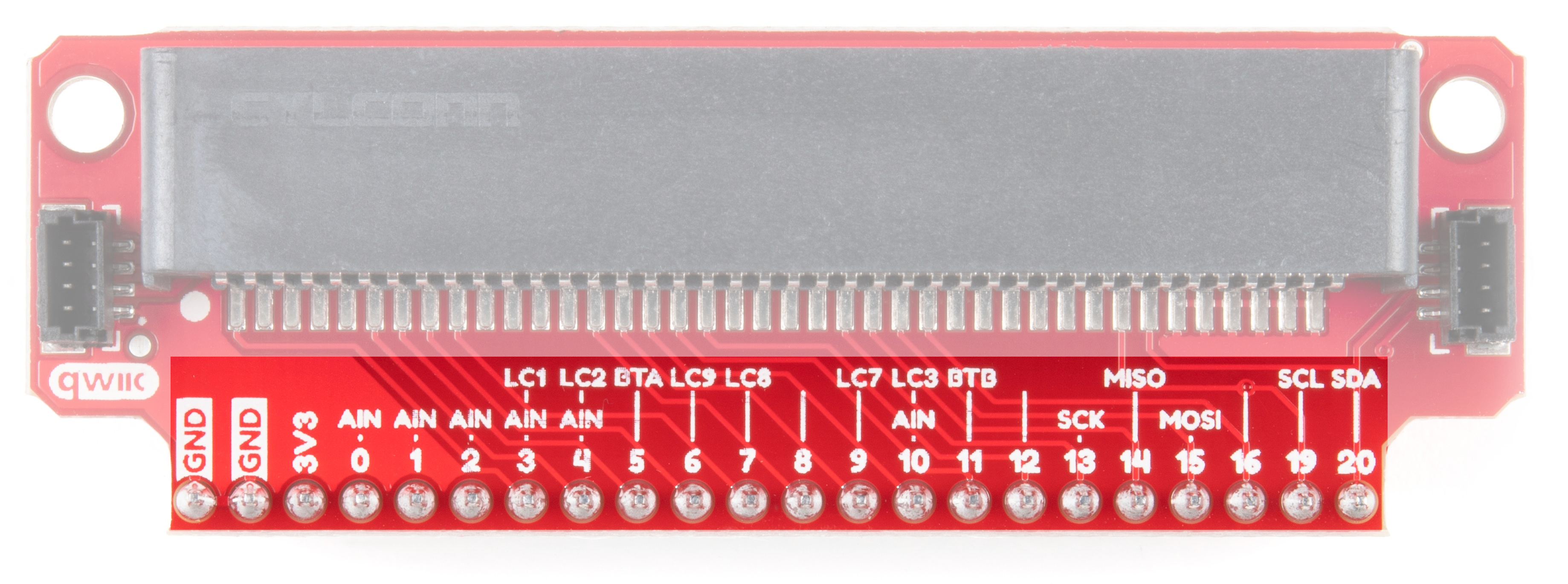
Pins
Most of the micro:bit's pins can be configured for one or more functions.
| Pin | Function 1 | Function 2 | Description |
|---|---|---|---|
| GND | Ground | ||
| GND | Ground | ||
| 3V3 | 3.3V | ||
| 0 | Analog In | Connected to large pin 0 | |
| 1 | Analog In | Connected to large pin 1 | |
| 2 | Analog In | Connected to large pin 2 | |
| 3 | Analog In | LED Column 1 | Controls part of LED array |
| 4 | Analog In | LED Column 2 | Controls part of LED array |
| 5 | Button A | Connected to Button A on micro:bit | |
| 6 | LED Column 9 | Controls part of LED array | |
| 7 | LED Column 8 | Controls part of LED array | |
| 8 | Open GPIO pin | ||
| 9 | LED Column 7 | Controls part of LED array | |
| 10 | Analog In | LED Column 3 | Controls part of LED array |
| 11 | Button B | Connected to Button B on micro:bit | |
| 12 | Open GPIO pin | ||
| 13 | SCK | GPIO or SPI clock | |
| 14 | MISO | GPIO or SPI MISO | |
| 15 | MOSI | GPIO or SPI MOSI | |
| 16 | Open GPIO pin | ||
| 19 | SCL | GPIO or I2 clock | |
| 20 | SDA | GPIO or I2 data |
Power Pin
The pin listed as 3V3 can be used as an input (regulated 3.3V, do not exceed 3.6V!) or an output if you plug a battery pack or USB into the micro:bit.
LCn Pins
The pins labeled with LCn (e.g. LC1, LC8) refer to pins that are used to control the LED array on the front of the micro:bit. You can use them as GPIO, but you'll often get weird patterns to show up on the LEDs, or when you write to the LED array, you may see unexpected behavior. If you use them as GPIO, we recommend disabling the LED display.
Qwiic Connectors
We've added a couple of Qwiic connectors on either side of the breakout board to take advantage of the I2C bus. For more information on the qwiic system, head on over to the Qwiic Connect System Landing Page.

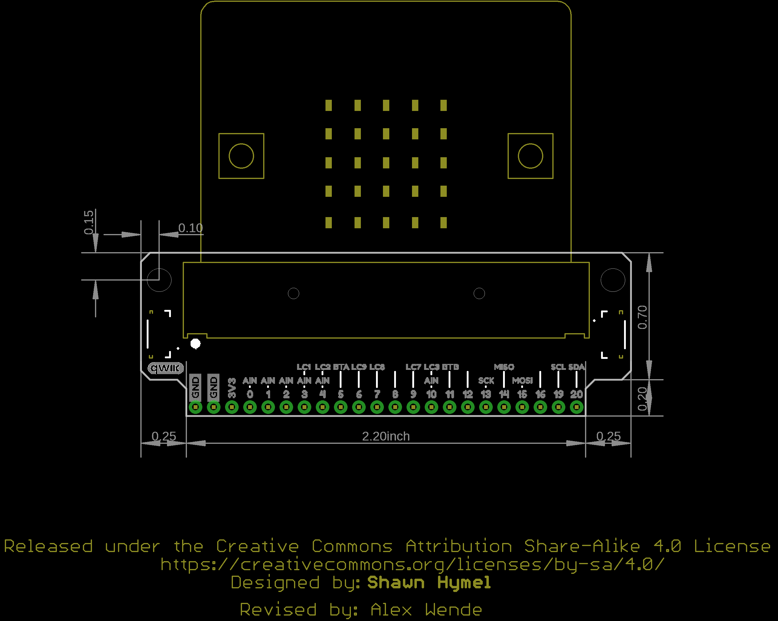
Board Outline
Hardware Assembly
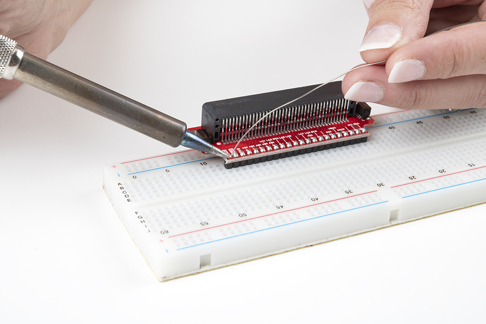
Attach Headers
If you have the version of the breakout board without headers, solder some breakaway headers to the board. You can also solder wire directly to the breakout.
Build Example Circuit
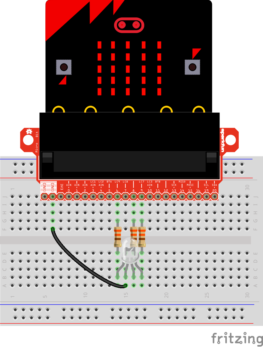
To begin, let's light up an RGB LED. Attach the micro:bit to the breakout board, place the breakout board onto a breadboard, and connect an RGB LED through 330 Ω resistors. Use the image below to aid you in wire up the circuit.
Remember, LEDs are polarized parts and can only work properly in one orientation. The longest leg of the LED goes where the black GND wire is in the circuit.
Example: Cycling Colors on an RGB LED
You can download the code from the emulator, or check out the project's page here:
Copy the .hex file to your micro:bit drive, and you should see a fancy array of colors appear on your LED!
Example: Qwiic Sensor
With the addition of Qwiic connectors on the micro:bit breakout board, you can take advantage of the sensors in our Qwiic Connect System. Let's take a "qwiic" look at how to attach and use Qwiic boards.
You can download the code from the emulator, or check out the project's page here:
Copy the .hex file to your micro:bit drive and you should see the temperature start scrolling by on your micro:bit's LED array!
Reading the sensor
There are a couple of things to point out here. In this example, we've used the Qwiic TMP117 sensor. Somewhat superfluous, given that the micro:bit has an onboard temp sensor but it's easy and I happened to have one handy.
To read the sensor, you need to be able to access the I2C bus. In MakeCode, under Pins->More, you'll find the blocks for reading these pins.
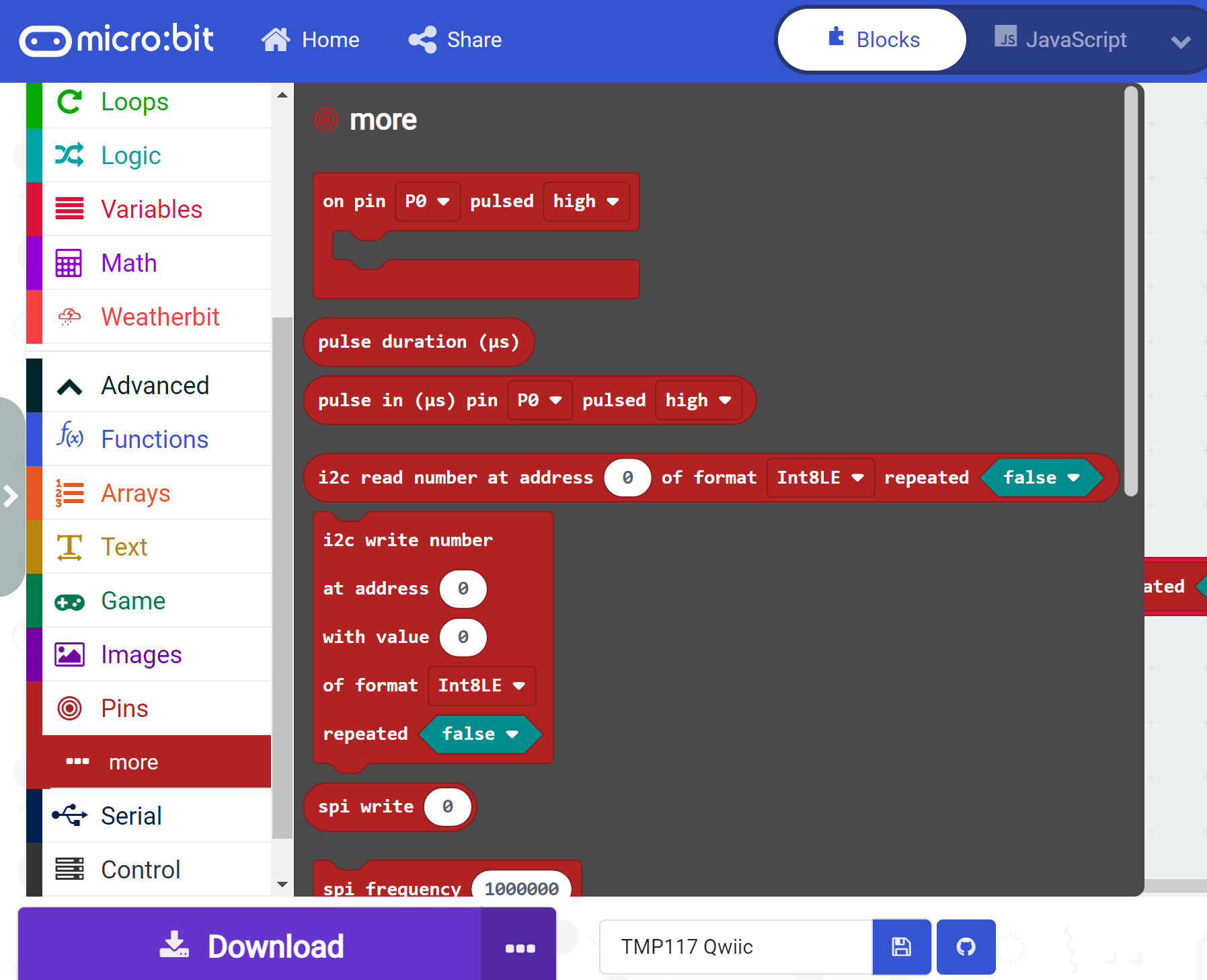
To determine the address, you'll need to find the address of your qwiic sensor (in this case, the TMP117's address is 0x48) and then convert that to decimal. I used a handy dandy calculator here. The hookup guides for each qwiic sensor will have their default address, as well as information on the datatype.
The multiplication step after getting the data from the sensor is specific to the TMP117 and is just a conversion to make the data legible to us mere humans.
Voila! Now grab a qwiic sensor and get to hacking!
Troubleshooting
If you need technical assistance and more information on a product that is not working as you expected, we recommend heading on over to the SparkFun Technical Assistance page for some initial troubleshooting.
If you don't find what you need there, the SparkFun Forums are a great place to find and ask for help. If this is your first visit, you'll need to create a Forum Account to search product forums and post questions.
Resources and Going Further
With the micro:bit breakout board, you can start introducing more sensors, lights, and motors into your project! For more information, check out these resources:
- Schematic
- Eagle Files
- GitHub Hardware Repo
- micro:bit Main Site
- Microsoft MakeCode
- MicroPython for micro:bit Editor
- Qwiic Connect System
Need some inspiration for your next project? Check out some of these related tutorials: