Making Custom Footprints in EAGLE
 Joel_E_B,
  TheoS
TheoS 
Introduction
This is a tutorial for the Eagle cad program, designed for intermediate level users. The idea is to import images of parts to create a customized footprint that matches the footprint on the component, and it can be done simply using the tools that Eagle provides.
As always, necessity is the mother of invention, and is what sparked using this Eagle tool here at SparkFun. Too many times we encountered problems with footprints having incorrect proportions, incorrect measurements, and often-times were too busy (too many things too close to each other). This led to reflow problems in our ovens, caused shifted parts, tombstones, and many, many jumpers to ground, especially on our QFN package ICs.
Our Testing and Quality Control Manager, Pete Lewis, figured out a good system to utilize Eagle's built-in image importer so that we could get exact footprints created for the problem parts.
Suggested Reading
As mentioned, this tutorial requires some intermediate skills with Eagle. If you would like a refresher on how to use Eagle as well as a few other skills, please visit these other tutorials.
Creating a Bitmap Image of the Footprint
The first step is the creation of a monochromatic Bitmap (*.bmp) image of the part you are customizing. Eagle really only likes to import images with solid colors, and black and white works very well. In this tutorial I will be using a Microstep Motor Driver (IC A4983SETTR-T) in a 28-QFN package. This IC can be found on the Quadstepper Motor Driver Board.
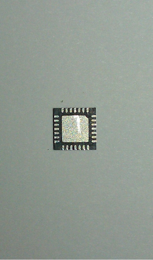
Using the macro setting on a digital camera (I recommend 8Mp or higher) take a picture of the underside of your part (where the legs or pads will be touching your board).
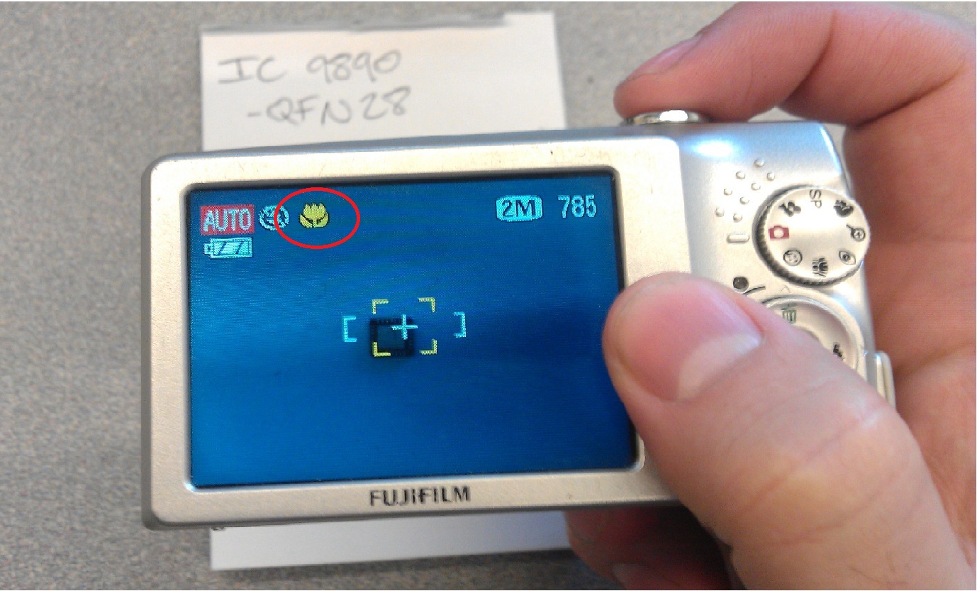
Try to position the part as straight and as centered as possible in the camera lens so that there will be less correction needed later. Use flash if necessary, but try to minimize shadows as much as possible.
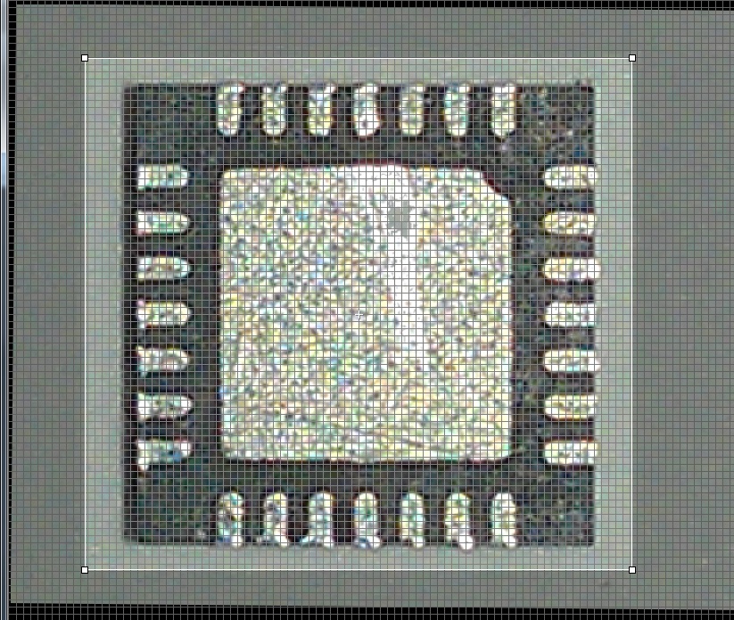
Once a picture of your liking has been taken, it's time to correct it, convert it to a Bitmap, and prepare it to be imported into Eagle. I used a program called Digital Photo Professional, because I like that it has a grid feature, but any program with an incremental rotate function and a saturation and contrast adjustment will work.
The goal is to make sure the part is absolutely straight/square in the frame so that it will be on-grid for Eagle.
Next, adjust the contrast (usually higher) and the saturation (always as low as it can be) to get the picture as close to black and white as possible.
At this point, it's a good idea to save a new version of the picture, and open that with the Windows default MS Paint, or something similar in Mac OS.
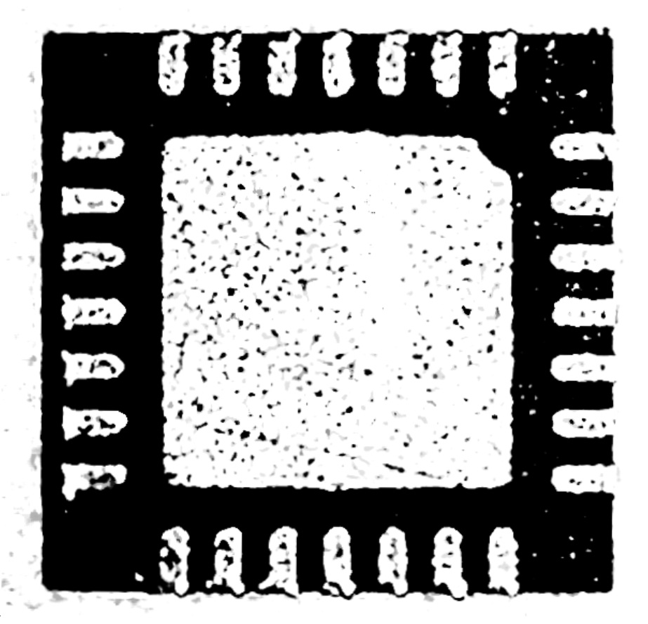
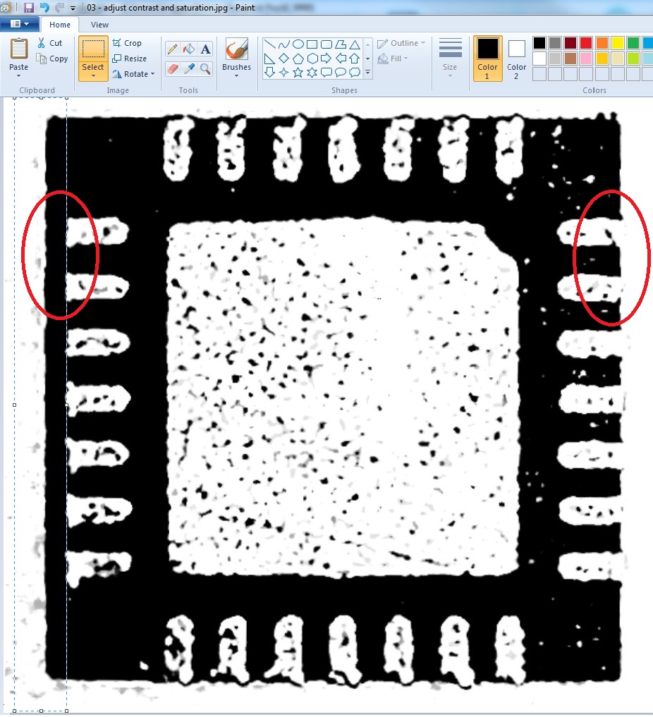
To clean up the shadows, use the CUT function (ctrl + X). Notice the righthand side, the black body is flush with the white pad. That is how you want the lefthand side to be as well. Simply highlight along the edge of the pads, and cut the shadow off.
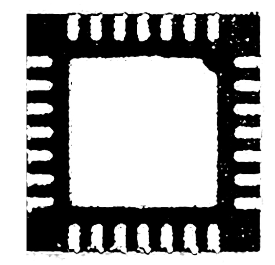
After that, use the ERASE tool to clean up the stray bits of black as much as possible. We want the white in the picture to be the metal pads, and we want them to be as clear as possible. This helps immensely when imported into Eagle, and it prevents a lot of confusion later on. The more pixels that are fixed now, the less time there will be spent trying to figure out where pads begin or end in Eagle.
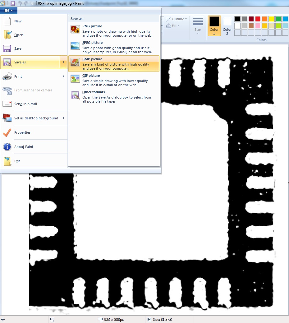
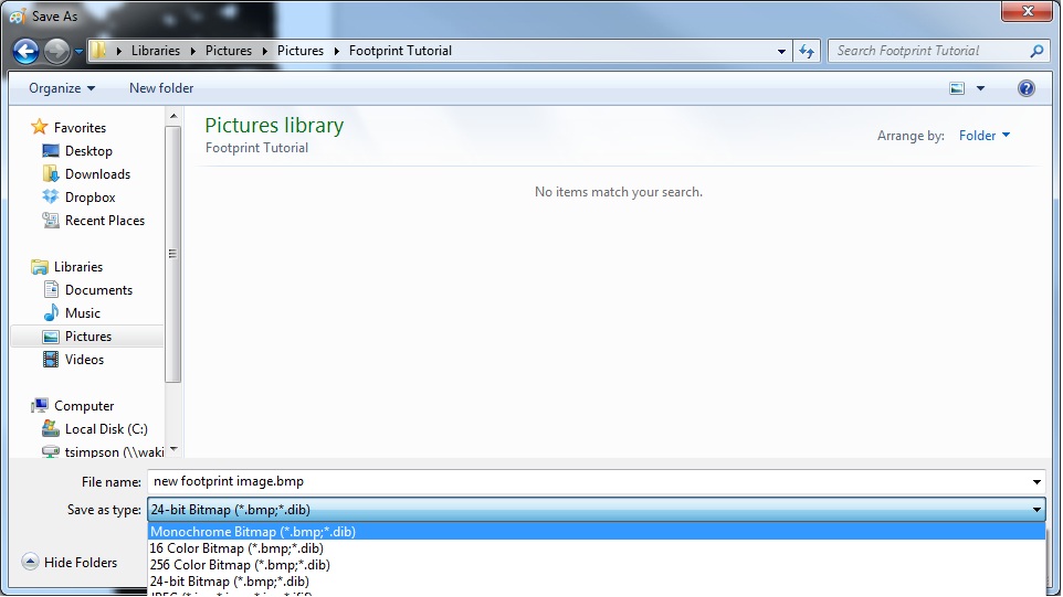
Saving the image as a monochromatic BMP is the easiest way to convert the picture into a usable form for Eagle.Click File → Save-As → and select Monochromatic Bitmap. Some programs have a dropdown menu, and this can be selected under “Type”.
Now you have a single-layer (monochromatic), black and white Bitmap image or your part, ready to be inserted into Eagle.
Importing the Bitmap Image into Eagle
Go ahead and open Eagle, and navigate to whichever library your part lives in. As stated in the title, this tutorial is not for building a footprint from scratch (although you can quite easily), rather it is for customizing an existing footprint to be exactly the right size and shape.
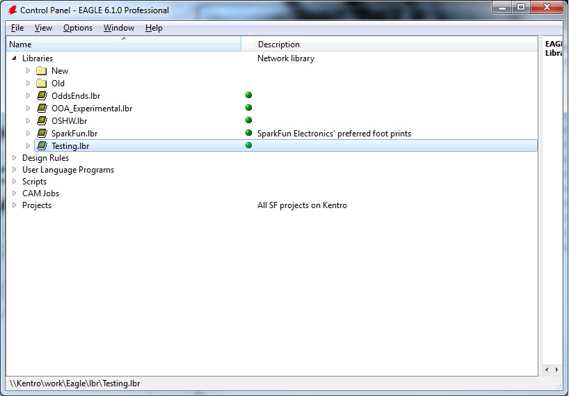
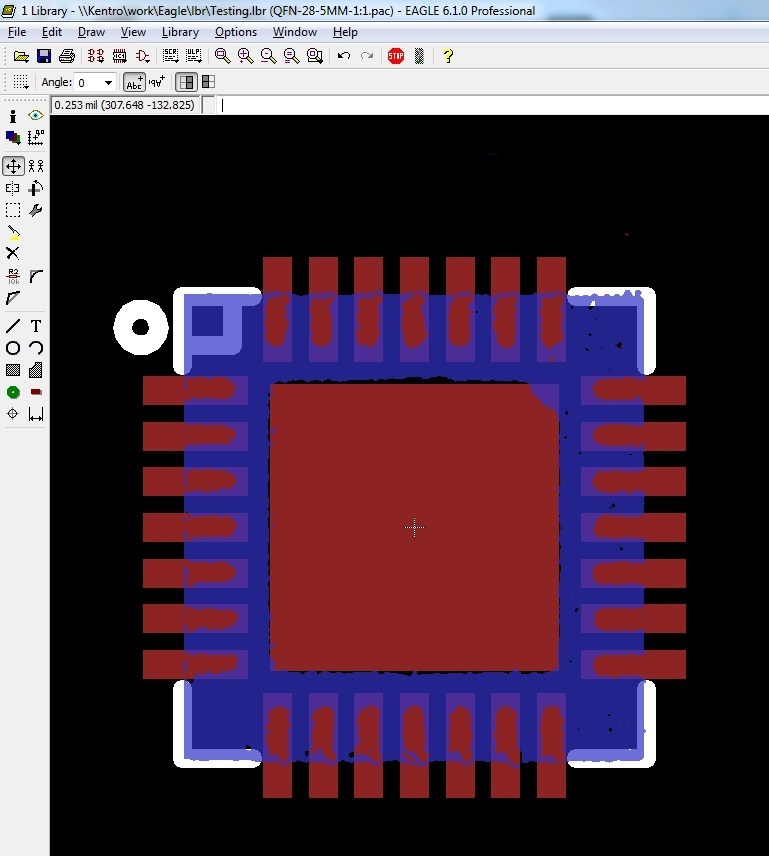
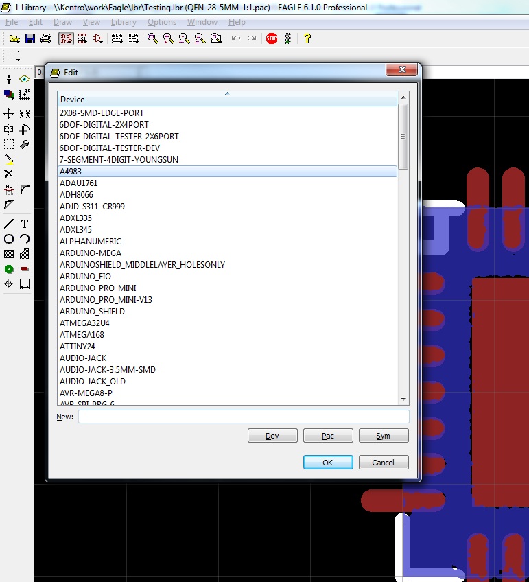
Once open, select your package using the little IC icon in your menu bar.
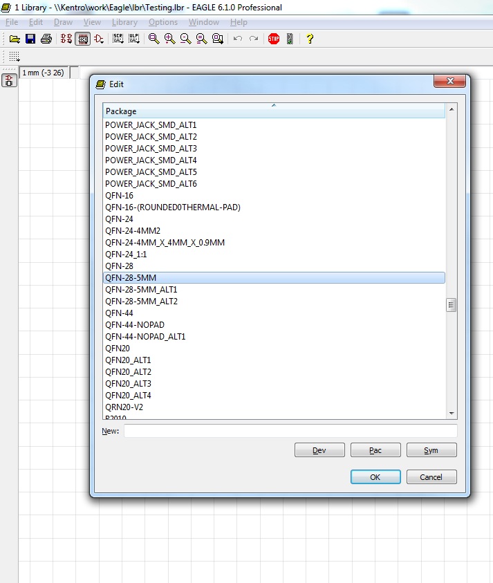
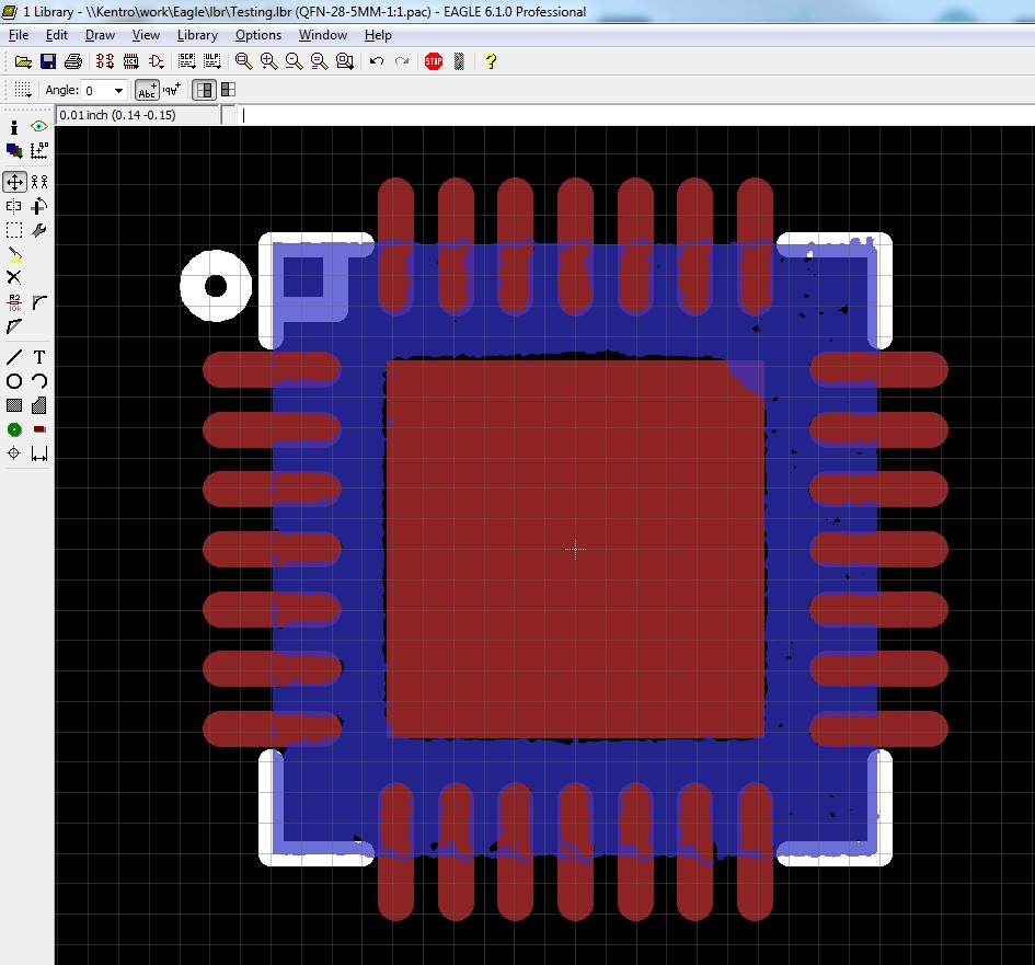
It will open something like this.
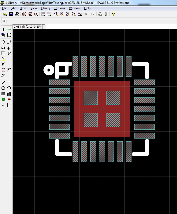
There are a couple of layers available here: red is the copper layer that represents the metal that will be exposed on your board, white stripes represents the stencil layer where solder paste will go if you decide to use reflow ovens as your soldering method (we use this method for all of our SMD components), and plain white represents the top silk layer that will print on your board.
We want to focus on the copper layer: the large center pad and the smaller foot-pads around it.
Before you do anything, it's a good idea to create a new package, copying the existing footprint from the one you just opened. Use the Group-Select tool (alt + F7) to highlight everything, and use the Copy tool to copy everything.
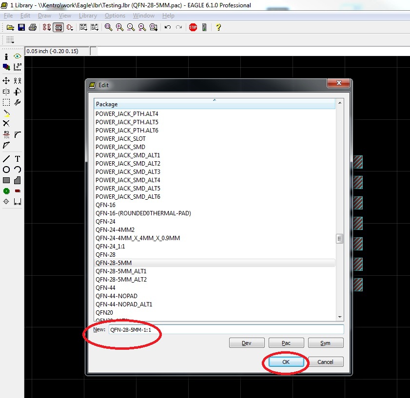
Open the Package list again, and, in the “New” bar, type the new name of your package. I always use the old name and then add “1:1” so that I know this is the one-to-one measured footprint.
Once you have created this new package, use the Paste tool to place everything from the old package.
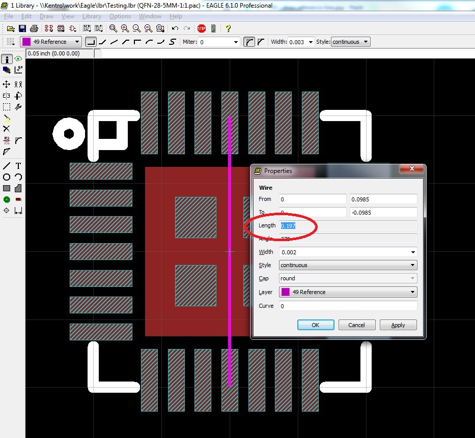
Next, measure your part with a pair of digital calipers. Pick the spot of the piece you measured in your Eagle package, and draw a line of precisely that length.
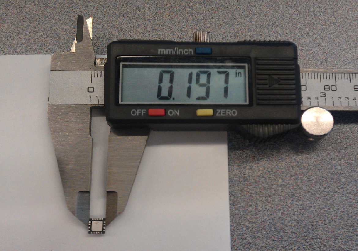
This is for reference purposes (I used the Reference Layer -- purple) so that we can scale our imported .bmp image.
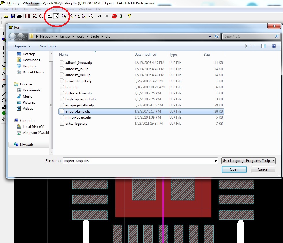
When you have your reference line laid out, click on the ULP button on your toolbar, and select “import-bmp”.This let's you set up parameters and run a script to plot pixels in Eagle based on a Bitmap image.
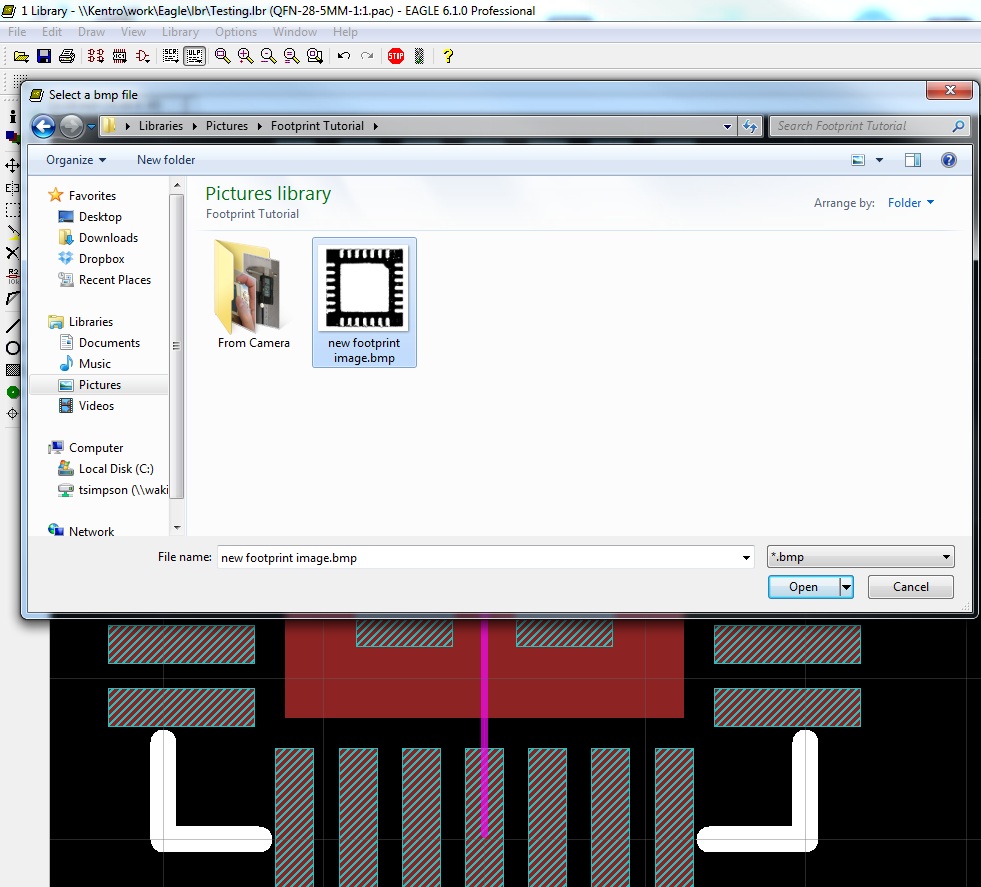
Select your Bitmap image, and then select the colors you wish to include.
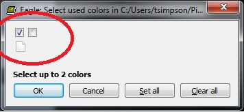
I always select only the first box, so that I only have one layer to work with on the imported image.
Next, you have to select your scale.
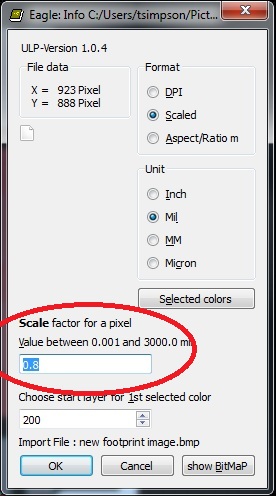
This is where the reference line comes into play. I always have to estimate the scale, run the script, and then measure the image against the reference line. If the image is too small, I select it all (alt + F7), delete it (F3), and re-import the image using a larger scale to run the script. If the image is too large, I use a smaller scale.
Sometimes it takes 5 or 6 importations to get the size exactly right, but it is worth it. Once you have the image in place, the rest is just fitting the copper layer to the pads in the image.
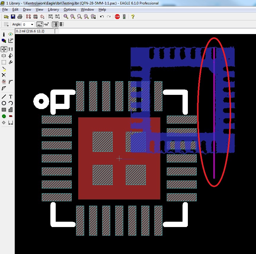
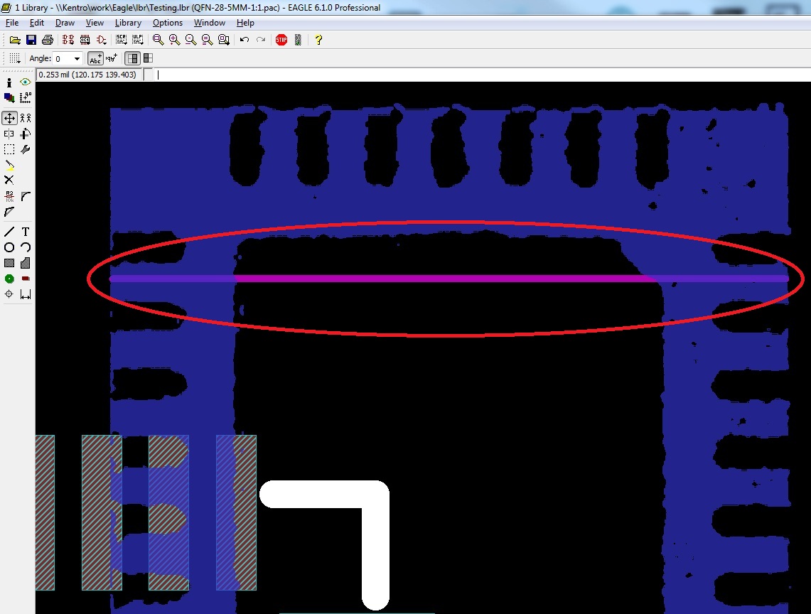
As you can see, the reference line matches the outside edges of the IC image. Also note that the color of the imported image is the color of the Eagle layer on which it was imported (200 is the default) and that by selecting only the first box of colors we get the component as positive space (blue) and the pads as negative space.
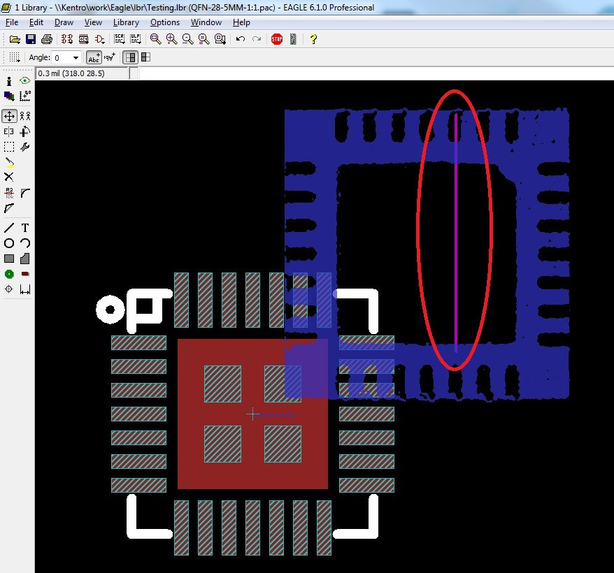
Moving the imported image over the center of the footprint might seem a bit tricky. First, note that the image is broken up into individual pixels that are each their own object. This means you cannot simply select one and move the whole image. It means you have to isolate the layer 200, select the whole image (alt + F7), and then move it over the rest of the footprint (F7). I used the large center pad as my reference point, making sure it is lined up with the center negative space on my imported image.

With that, you should now have an image of the correct footprint sizes and dimensions. Now let's see how to edit our part to match this 1:1 image.
Editing the Existing Footprint
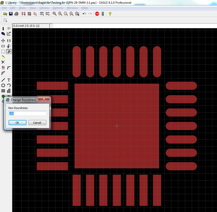
Chances are the existing footprint will be fairly close to the right size and spacing, but there are always better ways to set things up. For instance, in this example, the pads on the footprint are square, while the pads on the part are round.
Always match metal to metal wherever possible. This means that all the pads on the footprint should be the same size and shape as their counterparts on the part on which you are working.
Using the Change tool on the left toolbar, select Roundness and type 100 (for 100%). Then select each pad, and they will change from square to round.
After all the pads are round, move each individual pad into place, using the imported image as a reference. Note the righthand pads are lined up correctly while the upper and lower pads have not yet been moved.
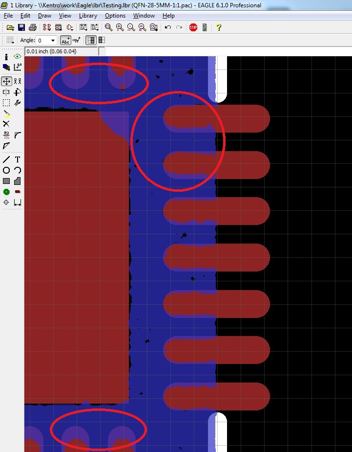
Remember that for the most part, footprints are quite small, so little moves in Eagle are even smaller in the real world. It's ok to just get things as close as you can. It doesn't have to be exactly right. I always make symmetrical moves when dealing with a symmetrical part (what I do to one side I do to all four sides), so I end up having to move pads into positions that look the best overall, and maybe not the best per individual pad.
Connecting the New Package to the Device
In order for you to be able to use the new package in Eagle, it must be connected to a device. Since we are just customizing an existing part, it's a pretty simple thing to do.
Open the Device list (next to Package on the toolbar), and select your device.
This opens a schematic picture of your device, along with all of the packages connected to it.
On the righthand side, select “New”.
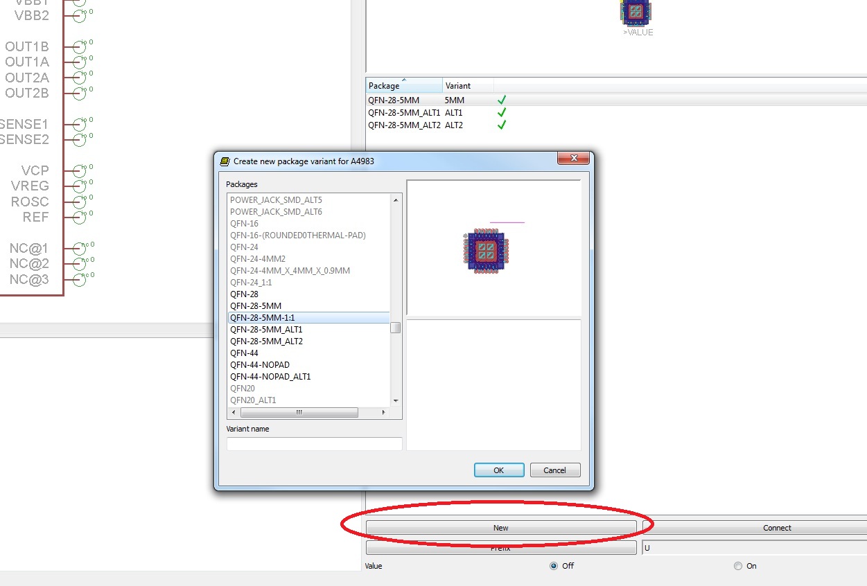
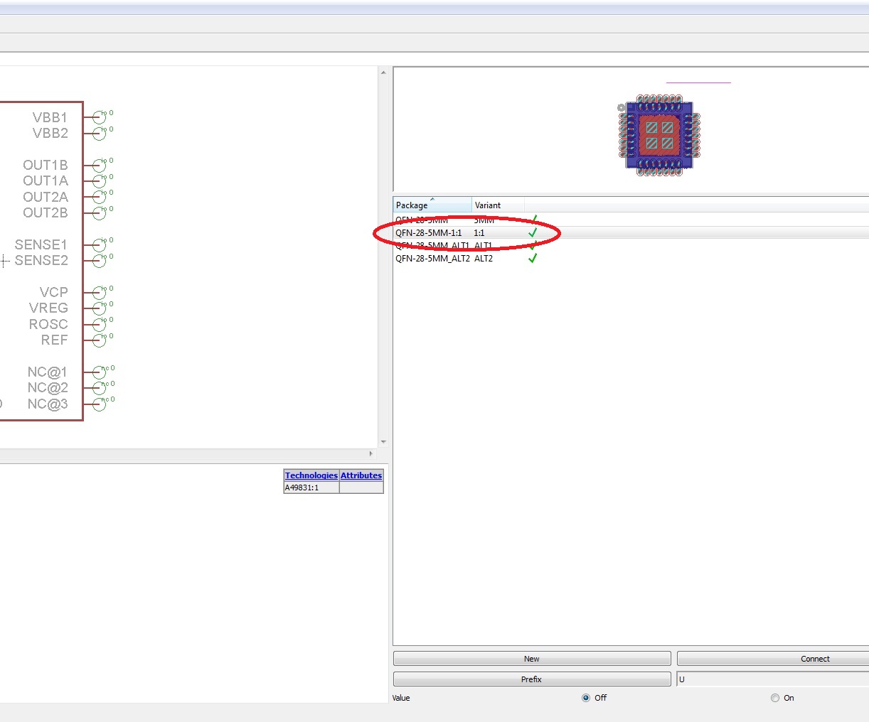
This brings up the package list, and you can select the one you just created.
You just created what Eagle calls a Variant. It's an alternate package associated with a device. Right-click on it and hit Rename.

I always rename this new Variant “1:1” so that all the Library files are consistent, but you can call it whatever you like.
Notice that there is that little yellow circle with an exclamation point next to the variant. This means that a package has been added to the device, but Eagle is not sure how to connect the pins associated with the pads.
With your variant selected, hit the Connect button.
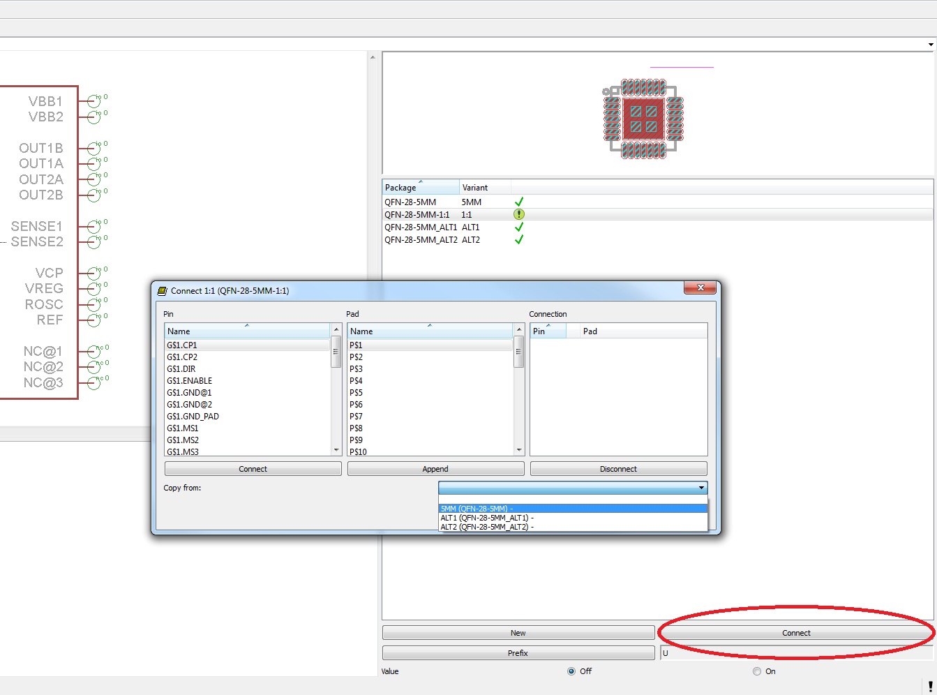
This brings up a list of all the pins on the Device, and all the pins on the package.
From the little dropdown menu, scroll to the original package name (if there is more than one package already associated with this device – in my case there are two more).
This connects your variant exactly like the original package, which is how you want it to be.
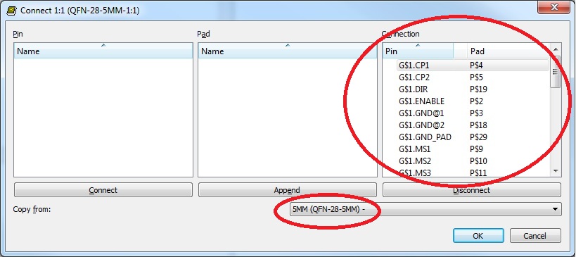
Once you click OK, you have completed the connections and your variant should get a check mark.
Now all that remains is to use this new package and on a board, or replace an existing package on a board if you have already used the library part somewhere in your designs.
Resources and Going Further
We hope you enjoyed this Eagle tutorial. Using this method, we have redesigned many boards here at SparkFun and solved a lot of our reflow and rework issues. We hope you use these tools to your advantage as well!
Check out these other SparkFun tutorials to learn more:
- Connector Basics
- Electronics Assembly
- Learn how to Stenciland Reflow with our Simon - Surface Mount Stenciling Kit