Large Digit Driver Hookup Guide
 Shawn Hymel
 Introduction
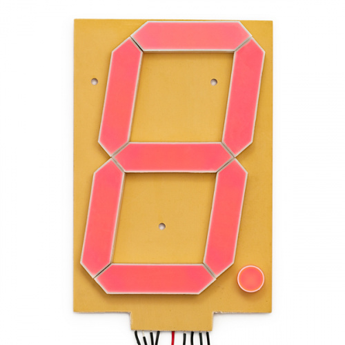
Large numerical displays are a great addition to any project where you want to be able to see information at a distance. Scorekeepers and lap timers would be a great application for large 7-segment LED displays. The Really Big 7-Segment Display (6.5") fits that bill nicely. Driving several displays at the same time would be handy, which is where the Large Digit Driver board comes in.
The Large Digit Driver can be soldered directly to the bottom of the 7-Segment Display.
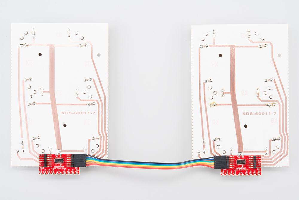
Several Large Digit Drivers can be chained together to create a display with multiple digits.
Covered in This Tutorial
In this tutorial, we will give you an overview of the Large Digit Driver and provide an example of hooking up the driver to an Arduino:
- Board Overview -- To begin, we'll go over each of the pins on the breakout board and their function.
- Hardware Hookup -- In this section, we'll show you how to hook the Large Digit Driver up to an Arduino.
- Example: One Large Digit -- Here, we give an example of an Arduino sketch to control one of the large 7-segment displays through the Large Digit Driver.
- Example: Two Large Digits -- We show how to daisy chain two large 7-segment displays together and control them with two Large Digit Drivers.
- Resources and Going Further -- This section gives some additional resources for getting more out of the Large Digit Driver.
Materials Used
To follow along with this tutorial, you will need the following materials. You may not need everything though depending on what you have. Add it to your cart, read through the guide, and adjust the cart as necessary. You will need a few components and tools to follow along with this tutorial. Here is the minimum parts needed for one 7-segment display.
For each additional digit you want to add, you will need:
Recommended Reading
Before getting started with the Large Digit Driver, there are a few concepts that you should be familiar with. Consider reading some of these tutorials before continuing:
- What is an Arduino? -- We will use an Arduino to control the Large Digit Driver
- Shift Registers -- The Large Digit Driver uses a shift register to move data to each digit
- How to Solder - Castellated Mounting Holes -- You will need to solder the Large Digit Driver to the back of the 7-segment LED display
What is an Arduino?
How to Solder: Castellated Mounting Holes
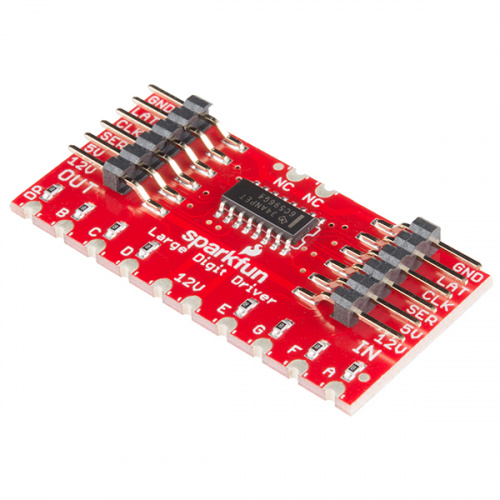
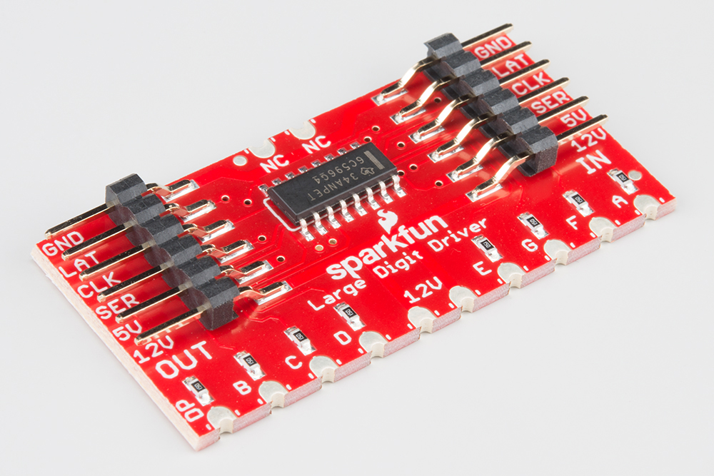
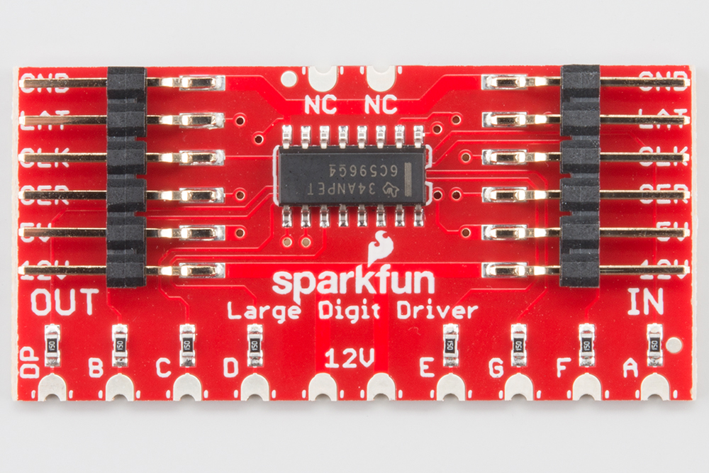
Board Overview
Pin Descriptions
The Large Digit Driver has 6 input pins and 6 output pins.
| IN Pin | Description |
|---|---|
| GND | Connect to ground |
| LAT | Data transfer in from SER on the rising edge of the latch pin |
| CLK | Data transfer in from SER on the rising edge of the clock pin |
| SER | Serial data in |
| 5V | Connect to power (5V) |
| 12V | Connect to power (12V) |
| OUT Pin | Description |
|---|---|
| GND | Connect to ground (used to provide a ground pin to the next Large Digit Driver in the chain) |
| LAT | Connect to the LAT pin on the next Large Digit Driver in the chain |
| CLK | Connect to the CLK pin on the next Large Digit Driver in the chain |
| SER | Serial data out to the next Large Digit Driver |
| 5V | 5V out to the next Large Digit Driver |
| 12V | 12V out to the next Large Digit Driver |
Hardware Hookup
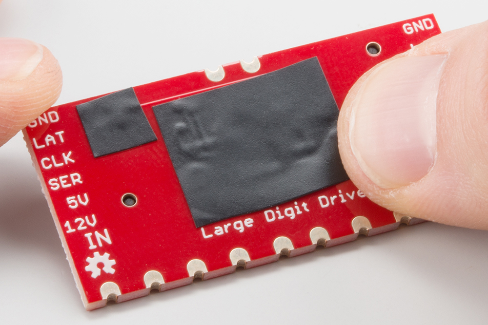
Protect the Board
Before you attach the Large Digit Driver to the 7-segment display, you will need to isolate the exposed vias on the back of the board. Some of the Driver boards are created with through-hole vias that are not covered with solder mask. As a result, this could likely short out the traces on the back of the 7-segment display.
We recommend using a piece of electrical tape or high temperature tape to cover the vias on the back of the Driver board.
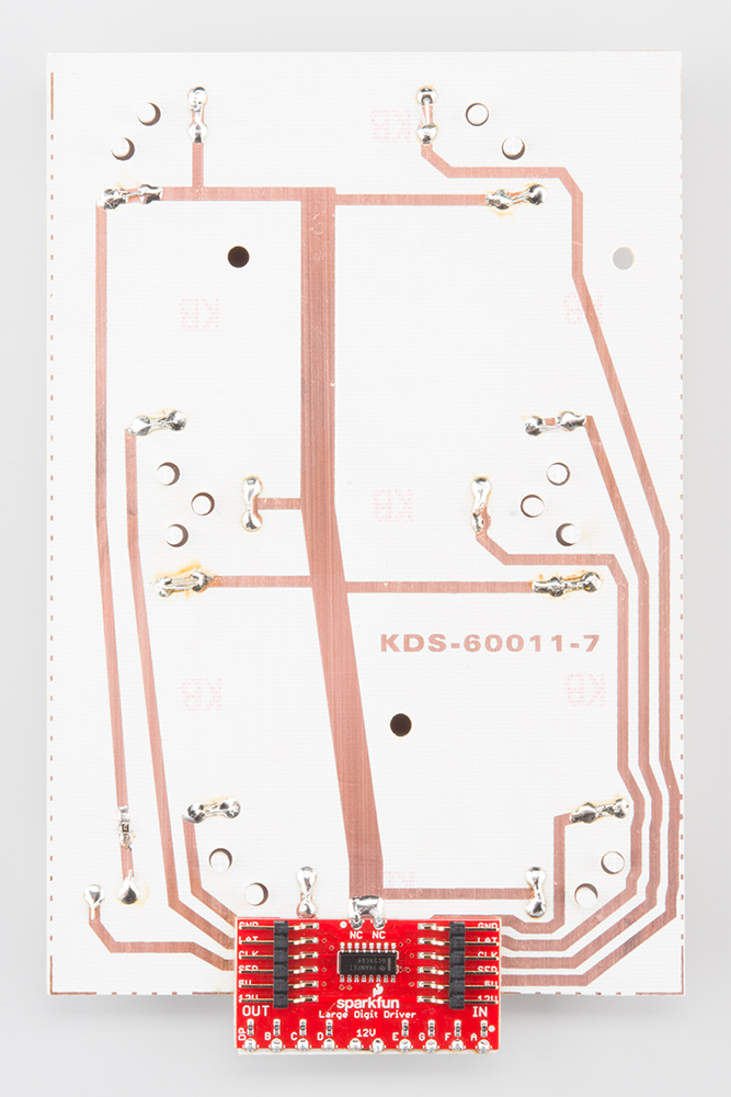
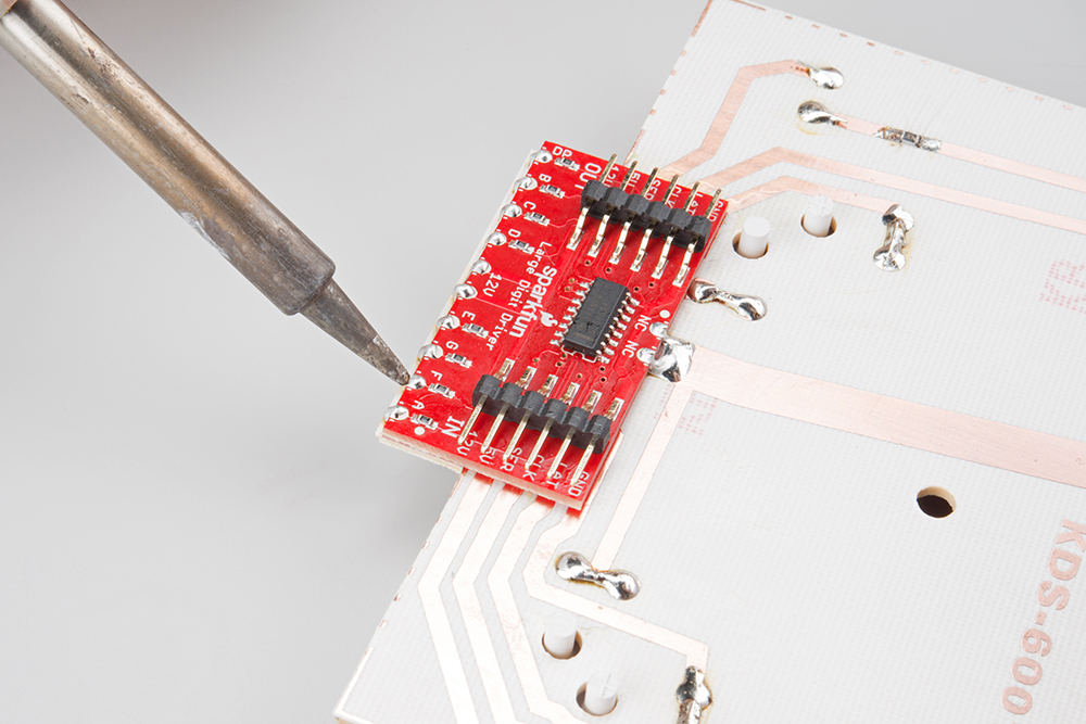
Attach the Board
You will need to solder the Large Digit Driver to the back of the 7-segment display. Have the Driver's 10 pins facing toward the bottom of the large 7-segment display and lined up with the traces on the back of the 7-segment display. Follow the Soldering Castellated Vias Guide to solder all 10 of the castellations as well as the 2 castellations at the top of the board (these should be attached to the 12V line and are just for mechanical support).
Connect the Board
We will be using the Arduino's regulated 5V and unregulated 12V (from the wall adapter) to power the 7-segment display and Large Digit Driver.
Connect the Large Digit Driver to the the following pins on the Arduino.
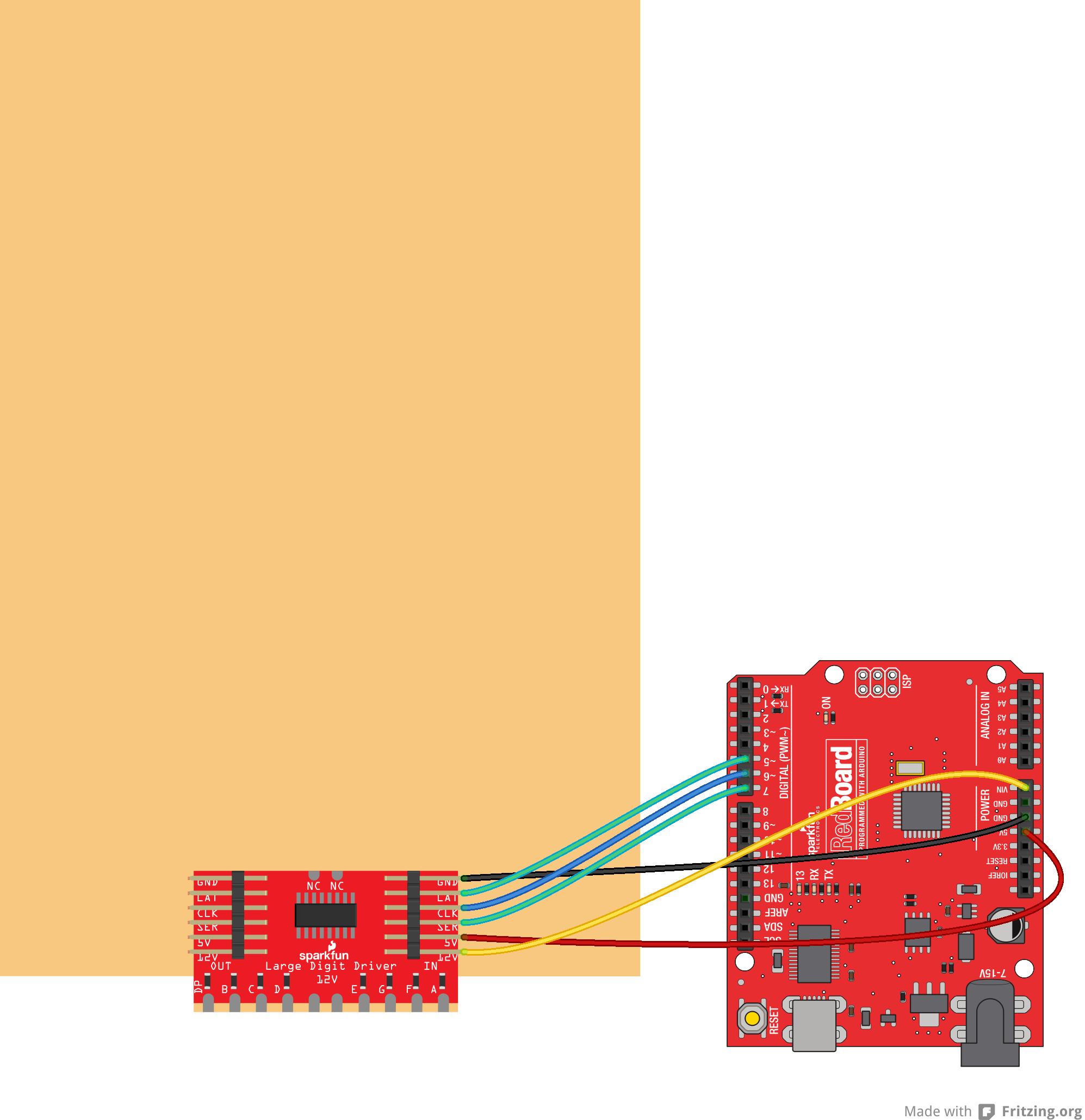
| Large Digit Driver | Arduino |
|---|---|
| GND | GND |
| LAT | 5 |
| CLK | 6 |
| SER | 7 |
| 5V | 5V |
| 12V | VIN |
Example: One Large Digit
Note: This example assumes you are using the latest version of the Arduino IDE on your desktop. If this is your first time using Arduino, please review our tutorial on installing the Arduino IDE.
If you have not previously installed an Arduino library, please check out our installation guide.Load the Single Digit Example Code
Plug your Arduino into your computer via USB cable. Open up the Arduino program and copy in the following sketch.
language:c
    /*
 Controlling large 7-segment displays
 By: Nathan Seidle
 SparkFun Electronics
 Date: February 25th, 2015
 License: This code is public domain but you buy me a beer if you use this and we meet someday (Beerware license).

 The large 7 segment displays can be controlled easily with a TPIC6C594 IC. This code demonstrates how to control
 one display.

 Here's how to hook up the Arduino pins to the Large Digit Driver

 Arduino pin 6 -> CLK (Green on the 6-pin cable)
 5 -> LAT (Blue)
 7 -> SER on the IN side (Yellow)
 5V -> 5V (Orange)
 Power Arduino with 12V and connect to Vin -> 12V (Red)
 GND -> GND (Black)

 There are two connectors on the Large Digit Driver. 'IN' is the input side that should be connected to
 your microcontroller (the Arduino). 'OUT' is the output side that should be connected to the 'IN' of addtional
 digits.

 Each display will use about 150mA with all segments and decimal point on.
*/

//GPIO declarations
//-=-=-=-=-=-=-=-=-=-=-=-=-=-=-=-=-=-=-=-=-=-=-=-=
byte segmentClock = 6;
byte segmentLatch = 5;
byte segmentData = 7;

//-=-=-=-=-=-=-=-=-=-=-=-=-=-=-=-=-=-=-=-=-=-=-=-=

void setup()
{
  Serial.begin(9600);
  Serial.println("Large Digit Driver Example");

  pinMode(segmentClock, OUTPUT);
  pinMode(segmentData, OUTPUT);
  pinMode(segmentLatch, OUTPUT);

  digitalWrite(segmentClock, LOW);
  digitalWrite(segmentData, LOW);
  digitalWrite(segmentLatch, LOW);

  int x = 0;
  while(1)
  {
    if(x == 9)
      postNumber(x, true); //Show decimal
    else
      postNumber(x, false);

    digitalWrite(segmentLatch, LOW);
    digitalWrite(segmentLatch, HIGH); //Register moves storage register on the rising edge of RCK
    delay(500);

    x++;
    x %= 10; //Reset x after 9

    Serial.println(x); //For debugging
  }
}

void loop()
{
  //showNumber(42); //Test pattern
}

//Takes a number and displays 2 numbers. Displays absolute value (no negatives)
void showNumber(float value)
{
  int number = abs(value); //Remove negative signs and any decimals

  //Serial.print("number: ");
  //Serial.println(number);

  for (byte x = 0 ; x < 2 ; x++)
  {
    int remainder = number % 10;

    postNumber(remainder, false);

    number /= 10;
  }

  //Latch the current segment data
  digitalWrite(segmentLatch, LOW);
  digitalWrite(segmentLatch, HIGH); //Register moves storage register on the rising edge of RCK
}

//Given a number, or '-', shifts it out to the display
void postNumber(byte number, boolean decimal)
{
  //    -  A
  //   / / F/B
  //    -  G
  //   / / E/C
  //    -. D/DP

#define a  1<<0
#define b  1<<6
#define c  1<<5
#define d  1<<4
#define e  1<<3
#define f  1<<1
#define g  1<<2
#define dp 1<<7

  byte segments;

  switch (number)
  {
    case 1: segments = b | c; break;
    case 2: segments = a | b | d | e | g; break;
    case 3: segments = a | b | c | d | g; break;
    case 4: segments = f | g | b | c; break;
    case 5: segments = a | f | g | c | d; break;
    case 6: segments = a | f | g | e | c | d; break;
    case 7: segments = a | b | c; break;
    case 8: segments = a | b | c | d | e | f | g; break;
    case 9: segments = a | b | c | d | f | g; break;
    case 0: segments = a | b | c | d | e | f; break;
    case ' ': segments = 0; break;
    case 'c': segments = g | e | d; break;
    case '-': segments = g; break;
  }

  if (decimal) segments |= dp;

  //Clock these bits out to the drivers
  for (byte x = 0 ; x < 8 ; x++)
  {
    digitalWrite(segmentClock, LOW);
    digitalWrite(segmentData, segments & 1 << (7 - x));
    digitalWrite(segmentClock, HIGH); //Data transfers to the register on the rising edge of SRCK
  }
}
Run
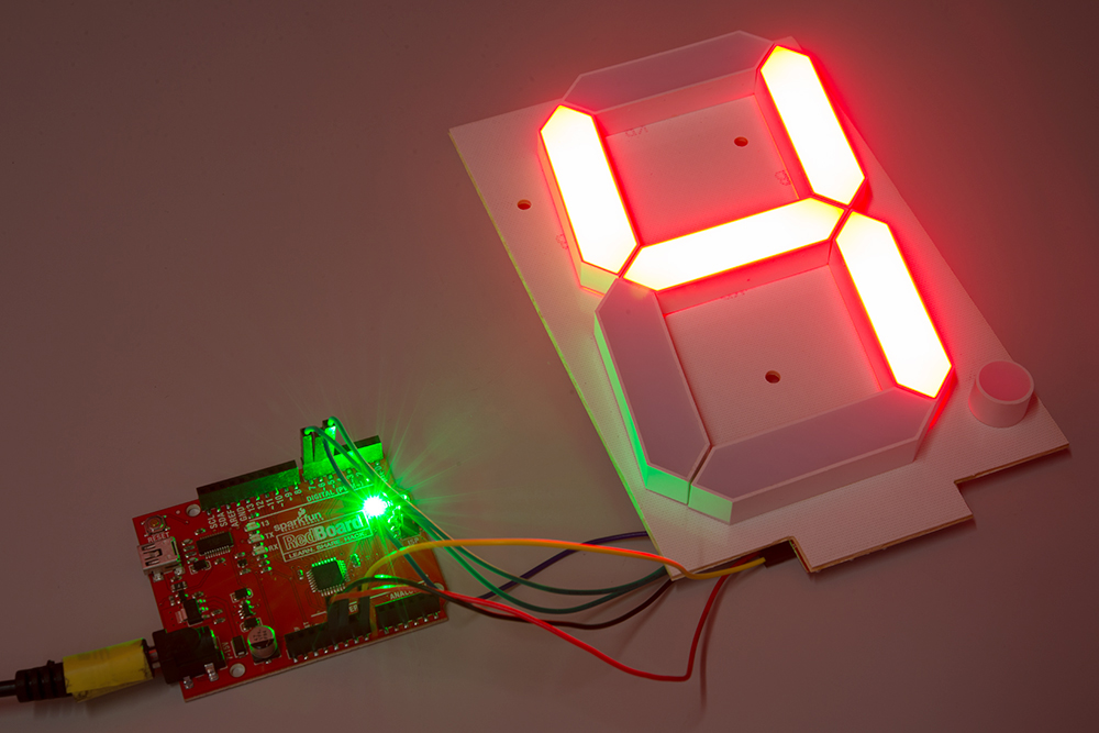
Upload the sketch to your Arduino, and plug the 12V adapter into the Arduino.

Flip the 7-segment display over. You should see it count the digits 0-9 (the decimal point will appear on 9).
Example: Two Large Digits
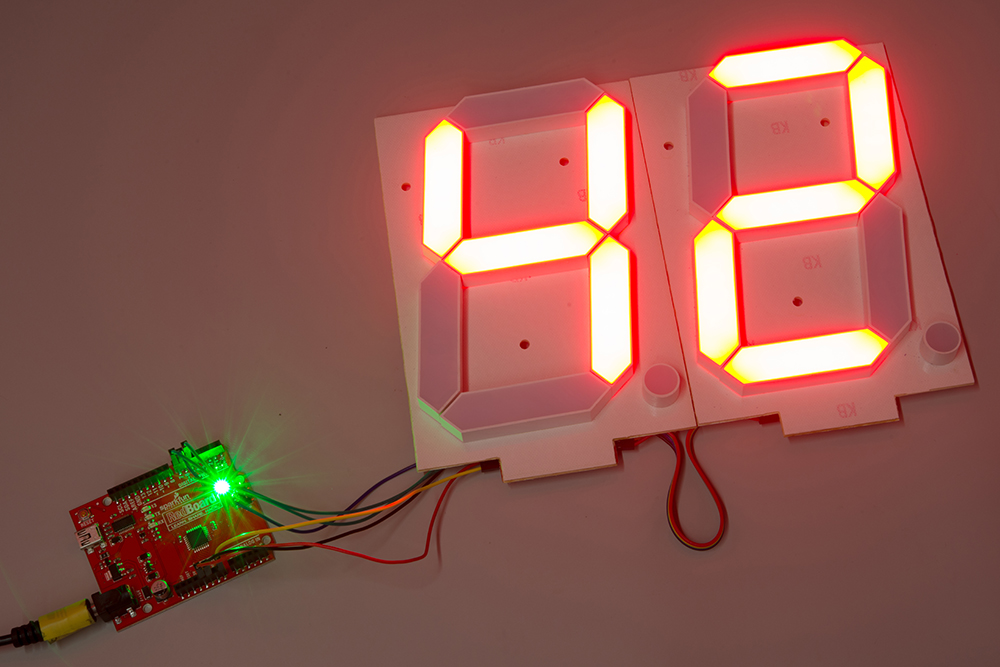
Attach a Second Digit
Use the 6-pin jumper wire to attach a second 7-segment display to the first display unit. Make sure that you connect GND of the OUT on the first display to the GND of the IN on the second display, LAT of the OUT on the first display to the LAT of the IN on the second display, and so on.
Load the Two Digit Example Code
Make sure the Arduino is plugged into your computer using a USB cable. Copy the following sketch into the Arduino program.
language:c
    /*
 Controlling large 7-segment displays
 By: Nathan Seidle
 SparkFun Electronics
 Date: February 25th, 2015
 License: This code is public domain but you buy me a beer if you use this and we meet someday (Beerware license).

 This code demonstrates how to post two numbers to a 2-digit display usings two large digit driver boards.

 Here's how to hook up the Arduino pins to the Large Digit Driver IN

 Arduino pin 6 -> CLK (Green on the 6-pin cable)
 5 -> LAT (Blue)
 7 -> SER on the IN side (Yellow)
 5V -> 5V (Orange)
 Power Arduino with 12V and connect to Vin -> 12V (Red)
 GND -> GND (Black)

 There are two connectors on the Large Digit Driver. 'IN' is the input side that should be connected to
 your microcontroller (the Arduino). 'OUT' is the output side that should be connected to the 'IN' of addtional
 digits.

 Each display will use about 150mA with all segments and decimal point on.

*/

//GPIO declarations
//-=-=-=-=-=-=-=-=-=-=-=-=-=-=-=-=-=-=-=-=-=-=-=-=
byte segmentClock = 6;
byte segmentLatch = 5;
byte segmentData = 7;

//-=-=-=-=-=-=-=-=-=-=-=-=-=-=-=-=-=-=-=-=-=-=-=-=

void setup()
{
  Serial.begin(9600);
  Serial.println("Large Digit Driver Example");

  pinMode(segmentClock, OUTPUT);
  pinMode(segmentData, OUTPUT);
  pinMode(segmentLatch, OUTPUT);

  digitalWrite(segmentClock, LOW);
  digitalWrite(segmentData, LOW);
  digitalWrite(segmentLatch, LOW);
}

int number = 0;

void loop()
{
  showNumber(number); //Test pattern
  number++;
  number %= 100; //Reset x after 99

  Serial.println(number); //For debugging

  delay(500);
}

//Takes a number and displays 2 numbers. Displays absolute value (no negatives)
void showNumber(float value)
{
  int number = abs(value); //Remove negative signs and any decimals

  //Serial.print("number: ");
  //Serial.println(number);

  for (byte x = 0 ; x < 2 ; x++)
  {
    int remainder = number % 10;

    postNumber(remainder, false);

    number /= 10;
  }

  //Latch the current segment data
  digitalWrite(segmentLatch, LOW);
  digitalWrite(segmentLatch, HIGH); //Register moves storage register on the rising edge of RCK
}

//Given a number, or '-', shifts it out to the display
void postNumber(byte number, boolean decimal)
{
  //    -  A
  //   / / F/B
  //    -  G
  //   / / E/C
  //    -. D/DP

#define a  1<<0
#define b  1<<6
#define c  1<<5
#define d  1<<4
#define e  1<<3
#define f  1<<1
#define g  1<<2
#define dp 1<<7

  byte segments;

  switch (number)
  {
    case 1: segments = b | c; break;
    case 2: segments = a | b | d | e | g; break;
    case 3: segments = a | b | c | d | g; break;
    case 4: segments = f | g | b | c; break;
    case 5: segments = a | f | g | c | d; break;
    case 6: segments = a | f | g | e | c | d; break;
    case 7: segments = a | b | c; break;
    case 8: segments = a | b | c | d | e | f | g; break;
    case 9: segments = a | b | c | d | f | g; break;
    case 0: segments = a | b | c | d | e | f; break;
    case ' ': segments = 0; break;
    case 'c': segments = g | e | d; break;
    case '-': segments = g; break;
  }

  if (decimal) segments |= dp;

  //Clock these bits out to the drivers
  for (byte x = 0 ; x < 8 ; x++)
  {
    digitalWrite(segmentClock, LOW);
    digitalWrite(segmentData, segments & 1 << (7 - x));
    digitalWrite(segmentClock, HIGH); //Data transfers to the register on the rising edge of SRCK
  }
}
Run
Upload the sketch to your Arduino, and plug in the 12V supply. The 7-segment display (now two digits!) should count from 00 to 99.
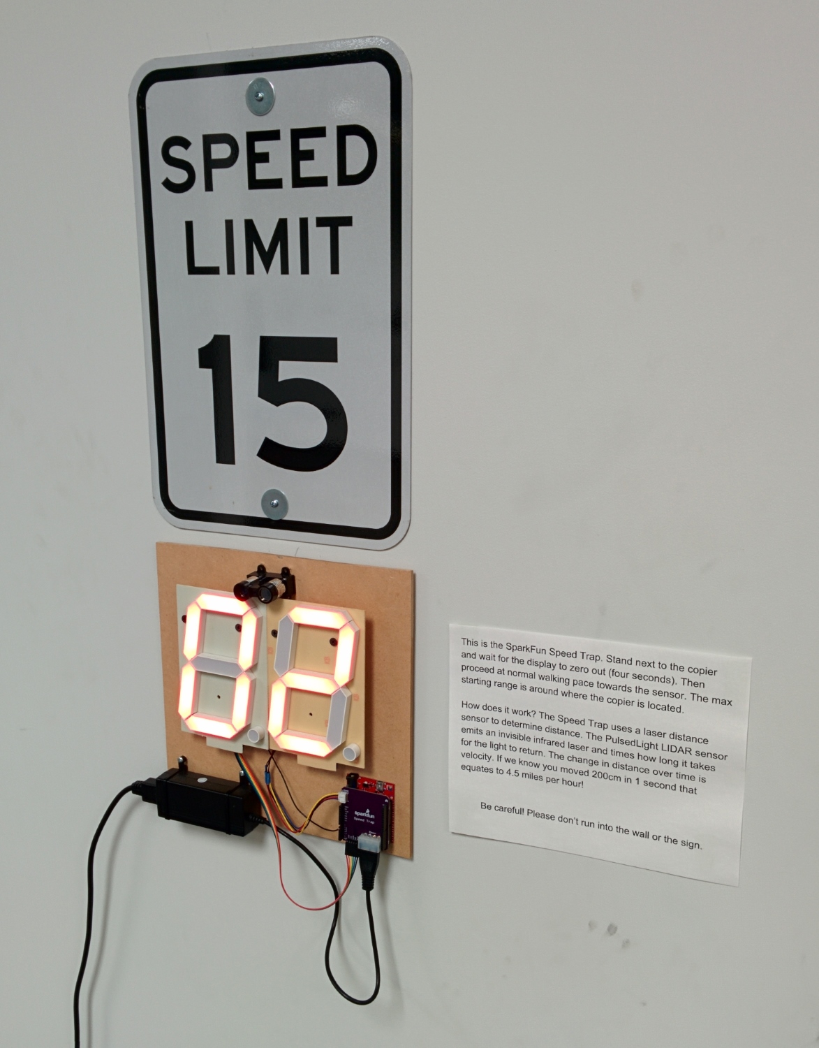
Example: Speed Trap
To demonstrate the displays we built a device that measures the distance from the wall to a human. As that distance changes we can caculate speed. We present: The SparkFun Speed Trap!
Here is a list of parts you'll need:
You can find the code and the PCB layout for the Speed Trap here. You don't need the custom PCB, it's fairly easy to build just with jumpers and a bit of soldering. You can also use the ATX power connector in the wishlist to save some time when using the 12V/5V power supply.
language:c
/*
 Displaying instantaneous speed from a LIDAR on two large 7-segment displays
 By: Nathan Seidle
 SparkFun Electronics
 Date: January 5th, 2015
 License: This code is public domain but you buy me a beer if you use this and we meet someday (Beerware license).

 The new LIDAR-Lite from PulsedLight is pretty nice. It outputs readings very quickly. From multiple distance
 readings we can calculate speed (velocity is the derivative of position).

 Here's how to hook up the Arduino pins to the Large Digit Driver backpack:
 Arduino pin 5 -> LAT
 6 -> CLK
 7 -> SER
 GND -> GND
 5V -> 5V
 VIN/Barrel Jack -> External 12V supply (this should power the LDD as well)

 You'll also need to connect the LIDAR to the Arduino:
 Arduino 5V -> LIDAR 5V
 GND -> GND
 A5 -> SCL
 A4 -> SDA
A0 -> Enable

*/

#include <Wire.h> //Used for I2C

#include <avr/wdt.h> //We need watch dog for this program

#define    LIDARLite_ADDRESS   0x62          // Default I2C Address of LIDAR-Lite.
#define    RegisterMeasure     0x00          // Register to write to initiate ranging.
#define    MeasureValue        0x04          // Value to initiate ranging.
#define    RegisterHighLowB    0x8F          // Register to get both High and Low bytes in 1 call.

//GPIO declarations
//-=-=-=-=-=-=-=-=-=-=-=-=-=-=-=-=-=-=-=-=-=-=-=-=

byte statLED = 13; //On board status LED
byte en_LIDAR = A0; //Low makes LIDAR go to sleep, high is normal operation

byte segmentLatch = 5; //Display data when this pin goes high
byte segmentClock = 6; //Clock one bit on each rising/falling edge
byte segmentSerial = 7; //Serial data in

//-=-=-=-=-=-=-=-=-=-=-=-=-=-=-=-=-=-=-=-=-=-=-=-=

long lastTime = 0;
long lastReading = 0;
int lastDistance = 265;
float newDistance;

const byte numberOfDeltas = 8;
float deltas[numberOfDeltas];
byte deltaSpot = 0; //Keeps track of where we are within the deltas array

//This controls how quickly the display updates
//Too quickly and it gets twitchy. Too slow and it doesn't seem like it's responding.
#define LOOPTIME 50

int maxMPH = 0; //Keeps track of what the latest fastest speed is
long maxMPH_timeout = 0; //Forget the max speed after some length of time

#define maxMPH_remember 3000 //After this number of ms the system will forget the max speed

void setup()
{
  wdt_reset(); //Pet the dog
  wdt_disable(); //We don't want the watchdog during init

  Serial.begin(115200);
  Serial.println("Speed Trap");

  Wire.begin();

  pinMode(en_LIDAR, OUTPUT);

  pinMode(segmentClock, OUTPUT);
  pinMode(segmentLatch, OUTPUT);
  pinMode(segmentSerial, OUTPUT);

  digitalWrite(segmentClock, LOW);
  digitalWrite(segmentLatch, LOW);
  digitalWrite(segmentSerial, LOW);

  pinMode(statLED, OUTPUT);

  Serial.println("Coming online");

  enableLIDAR();
  while(readLIDAR() == 0)
  {
    Serial.println("Failed LIDAR read");
    delay(100);
  }

  showSpeed(42); //Test pattern

  delay(500);

  /*postNumber('c', false);
  postNumber(' ', false);
  digitalWrite(segmentLatch, LOW);
  digitalWrite(segmentLatch, HIGH); //Register moves storage register on the rising edge of RCK
  delay(2000);*/

  wdt_reset(); //Pet the dog
  wdt_enable(WDTO_250MS); //Unleash the beast
}

void loop()
{
  wdt_reset(); //Pet the dog

  //Each second blink the status LED
  if (millis() - lastTime > 1000)
  {
    lastTime = millis();

    if (digitalRead(statLED) == LOW)
      digitalWrite(statLED, HIGH);
    else
      digitalWrite(statLED, LOW);
  }

  //Take a reading every 50ms
  if (millis() - lastReading > (LOOPTIME-1)) // 49)
  {
    lastReading = millis();

    //Every loop let's get a reading
    newDistance = readLIDAR(); //Go get distance in cm

    //Error checking
    if(newDistance > 1200) newDistance = 0;

    int deltaDistance = lastDistance - newDistance;
    lastDistance = newDistance;

    //Scan delta array to see if this new delta is sane or not
    boolean safeDelta = true;
    for(int x = 0 ; x < numberOfDeltas ; x++)
    {
      //We don't want to register jumps greater than 30cm in 50ms
      //But if we're less than 1000cm then maybe
      //30 works well
      if( abs(deltaDistance - deltas[x]) > 40) safeDelta = false;
    }

    //Insert this new delta into the array
    if(safeDelta)
    {
      deltas[deltaSpot++] = deltaDistance;
      if (deltaSpot > numberOfDeltas) deltaSpot = 0; //Wrap this variable
    }

    //Get average of the current deltas array
    float avgDeltas = 0.0;
    for (byte x = 0 ; x < numberOfDeltas ; x++)
      avgDeltas += (float)deltas[x];
    avgDeltas /= numberOfDeltas;

    //22.36936 comes from a big coversion from cm per 50ms to mile per hour
    float instantMPH = 22.36936 * (float)avgDeltas / (float)LOOPTIME;

    instantMPH = abs(instantMPH); //We want to measure as you walk away

    ceil(instantMPH); //Round up to the next number. This is helpful if we're not displaying decimals.

    if(instantMPH > maxMPH)
    {
      showSpeed(instantMPH);

      maxMPH = instantMPH;
      maxMPH_timeout = millis();
    }
    else //maxMPH is king
    {
      showSpeed(maxMPH);
    }

    if(millis() - maxMPH_timeout > maxMPH_remember)
    {
      maxMPH = 0;
      showSpeed(0);
    }

    Serial.print("raw: ");
    Serial.print(newDistance);
    Serial.print(" delta: ");
    Serial.print(deltaDistance);
    Serial.print(" cm distance: ");
    Serial.print(newDistance * 0.0328084, 2); //Convert to ft
    Serial.print(" ft delta:");
    Serial.print(abs(avgDeltas));
    Serial.print(" speed:");
    Serial.print(abs(instantMPH), 2);
    Serial.print(" mph");
    Serial.println();
  }

}

//A watch dog friendly delay
void petFriendlyDelay(int timeMS)
{
  long current = millis();

  while(millis() - current < timeMS)
  {
    delay(1);
    wdt_reset(); //Pet the dog
  }
}

//Get a new reading from the distance sensor
int readLIDAR(void)
{
  int distance = 0;

  Wire.beginTransmission((int)LIDARLite_ADDRESS); // transmit to LIDAR-Lite
  Wire.write((int)RegisterMeasure); // sets register pointer to  (0x00)
  Wire.write((int)MeasureValue); // sets register pointer to  (0x00)
  Wire.endTransmission(); // stop transmitting

  delay(20); // Wait 20ms for transmit
  wdt_reset(); //Pet the dog

  Wire.beginTransmission((int)LIDARLite_ADDRESS); // transmit to LIDAR-Lite
  Wire.write((int)RegisterHighLowB); // sets register pointer to (0x8f)
  Wire.endTransmission(); // stop transmitting

  delay(20); // Wait 20ms for transmit
  wdt_reset(); //Pet the dog

  Wire.requestFrom((int)LIDARLite_ADDRESS, 2); // request 2 bytes from LIDAR-Lite

  if (Wire.available() >= 2) // if two bytes were received
  {
    distance = Wire.read(); // receive high byte (overwrites previous reading)
    distance = distance << 8; // shift high byte to be high 8 bits
    distance |= Wire.read(); // receive low byte as lower 8 bits
    return (distance);
  }
  else
  {
    Serial.println("Read fail");
    disableLIDAR();
    delay(100);
    enableLIDAR();

    return(0);
  }
}

//Takes a speed and displays 2 numbers. Displays absolute value (no negatives)
void showSpeed(float speed)
{
  int number = abs(speed); //Remove negative signs and any decimals

  //Serial.print("number: ");
  //Serial.println(number);

  for (byte x = 0 ; x < 2 ; x++)
  {
    int remainder = number % 10;

    postNumber(remainder, false);

    number /= 10;
  }

  //Latch the current segment data
  digitalWrite(segmentLatch, LOW);
  digitalWrite(segmentLatch, HIGH); //Register moves storage register on the rising edge of RCK
}

//Given a number, or '-', shifts it out to the display
void postNumber(byte number, boolean decimal)
{
  //    -  A
  //   / / F/B
  //    -  G
  //   / / E/C
  //    -. D/DP

#define a  1<<0
#define b  1<<6
#define c  1<<5
#define d  1<<4
#define e  1<<3
#define f  1<<1
#define g  1<<2
#define dp 1<<7

  byte segments;

  //This method uses 7946 bytes
  switch (number)
  {
    case 1: segments = b | c; break;
    case 2: segments = a | b | d | e | g; break;
    case 3: segments = a | b | c | d | g; break;
    case 4: segments = f | g | b | c; break;
    case 5: segments = a | f | g | c | d; break;
    case 6: segments = a | f | g | e | c | d; break;
    case 7: segments = a | b | c; break;
    case 8: segments = a | b | c | d | e | f | g; break;
    case 9: segments = a | b | c | d | f | g; break;
    case 0: segments = a | b | c | d | e | f; break;
    case ' ': segments = 0; break;
    case 'c': segments = g | e | d; break;
    case '-': segments = g; break;
  }

  //The method uses 7954 bytes
  /*if(number == 1) segments = b|c;
  if(number == 2) segments = a|b|d|e|g;
  if(number == 3) segments = a|b|c|d|g;
  if(number == 4) segments = f|g|b|c;
  if(number == 5) segments = a|f|g|c|d;
  if(number == 6) segments = a|f|g|e|c|d;
  if(number == 7) segments = a|b|c;
  if(number == 8) segments = a|b|c|d|e|f|g;
  if(number == 9) segments = a|b|c|d|f|g;
  if(number == 0) segments = a|b|c|d|e|f;
  if(number == ' ') segments = 0;
  if(number == 'c') segments = g | e | d;
  if(number == '-') segments = g;*/

  if (decimal) segments |= dp;

  for (byte x = 0 ; x < 8 ; x++)
  {
    digitalWrite(segmentClock, LOW);
    digitalWrite(segmentSerial, segments & 1 << (7 - x));
    digitalWrite(segmentClock, HIGH); //Data transfers to the register on the rising edge of SRCK
  }
}

//Sometimes the LIDAR stops responding. This causes it to reset
void disableLIDAR()
{
  digitalWrite(en_LIDAR, LOW);
}

void enableLIDAR()
{
  digitalWrite(en_LIDAR, HIGH);
}

//Takes an average of readings on a given pin
//Returns the average
int averageAnalogRead(byte pinToRead)
{
  byte numberOfReadings = 8;
  unsigned int runningValue = 0;

  for (int x = 0 ; x < numberOfReadings ; x++)
    runningValue += analogRead(pinToRead);
  runningValue /= numberOfReadings;

  return (runningValue);
}
Troubleshooting
If you need technical assistance and more information on a product that is not working as you expected, we recommend heading on over to the SparkFun Technical Assistance page for some initial troubleshooting.
If you don't find what you need there, the SparkFun Forums are a great place to find and ask for help. If this is your first visit, you'll need to create a Forum Account to search product forums and post questions.
Can the Large 7-Segment Displays Work Outside?
For long term installations, we do not recommend installing the large digit outside under extreme weather conditions (especially in the heat). Additionally, it can be hard to view the LEDs in direct sunlight during the afternoon.
If you do use the large 7-segment displays outside, we recommend using red plexiglass to improve on the visibility. It would be better to have it under a tent or shadow when viewing the digits outside.
Resources and Going Further
Now that we have tested the large 7-segment displays, they are ready to be used in your project! Feel free to change the code to display other numbers or symbols on the displays.
Resources
Here are some additional resource to help you with the Large Digit Driver:
- Large 7-Segment Display Datasheet
- Datasheet for the shift register on the Large Digit Driver
- Large Digit Driver GitHub Repository
Check out this tutorial that a customer created for using the large digit display driver with a Raspberry Pi:
Other Tutorials
What will you make with the Large Digit Driver? If you need some inspiration, check out these related tutorials: