Gram Piano Assembly Guide
This Tutorial is Retired!
This tutorial covers concepts or technologies that are no longer current. It's still here for you to read and enjoy, but may not be as useful as our newest tutorials.
 JordanDee
 Introduction
The Gram Piano is a through-hole soldering kit that transforms from a pile of hardware into a tiny piano, ready for the playing. Once built, you can play an octave worth of notes using the capacitive touch keys. The pre-installed software also lets you switch between three octaves using a potentiometer and play a melody with the press of a button. Building and playing with this kit will teach you various skills related to soldering, electronics, music, and programming.
Covered in This Tutorial
This guide will explain the assembly process, the gram piano's default functionality, and will provide an overview of the pre-installed software. After building and playing with the board's default settings, you can customize your board to your liking by diving into the source code.
Suggested Reading
This tutorial assumes you have prior knowledge of the topics mentioned below. If you are unfamiliar with any, please feel free to read up on that subject and then return to this tutorial.
- How to Solder - The Basics of Through-hole Soldering - The first and most importnat skill needed for any soldering kit!
- Polarity - Learn which components have polarity and need more attention when soldering.
- Pulse Width Modulation - PWM is used to drive the speaker on the board.
- Arduino's Tone Reference - This will help us generate the tones that emit when a certain key is pressed.
- Installing an Arduino Library - Learn how to install any libraries needed for the Gram Piano, such as the CapSense library.
- Arduino's Capacitive Sense Library - Speaking of...
- Arduino's Capacitive Sense Library Reference - Learn how the Cap Sense Library works.
Required Materials
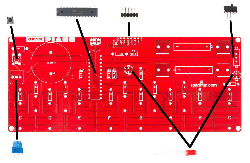
The Gram Piano Kit comes with a printed circuit board and a handful of components shown in the photo below.
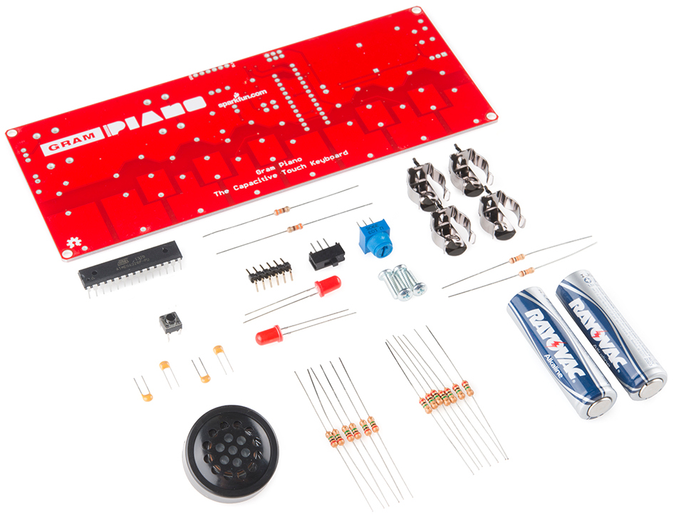
Full Kit Part List
- x1 Gram Piano PCB
- x1 PCB Speaker
- x2 AA Batteries
- x2 AA Battery Holders
- x1 Atmel AVR 328 Microcontroller
- x1 Mini Power Switch
- x1 Mini Push Button
- x1 10k Ohm Potentiometer
- x2 Red 5mm LED's
- x4 .1 uF Ceramic Capacitors
- x2 330 Ohm Resistors
- x2 10k Ohm Resistors
- x13 2M Ohm Resistors
- x1 6 Pin Right-angle Male Header
- x4 3/8" 4-40 Nylon Standoffs
- x4 3/8" 4-40 Screws
Extra Tools/Parts You'll Need (Not included with the Gram Piano)
Now, let's get to building!
Assembly
The Gram Piano is a through hole soldering kit. If you have never soldered before, it is strongly advised that you read through SparkFun's soldering tutorial first.
This page will give you a suggested approach to tackling the task of building this kit. In general, it is recommended to solder the smaller components first, then the larger ones. While this method is not absolutely crucial, it is easier to solder the smaller components if larger components are not blocking the way of your soldering iron.
Make sure each component is placed on the top side of the board (the side with white silkscreen that outlines the parts and labels the piano keys), so all the soldering can be done on the back side. Always double check your placement before soldering. It's also good practice to solder one pin, then check your work, before soldering the rest of the pins for any component. That way, if a mistake is made, only one solder joint has to be heated up to take the component back out of the board and replaced correctly.
Step by step
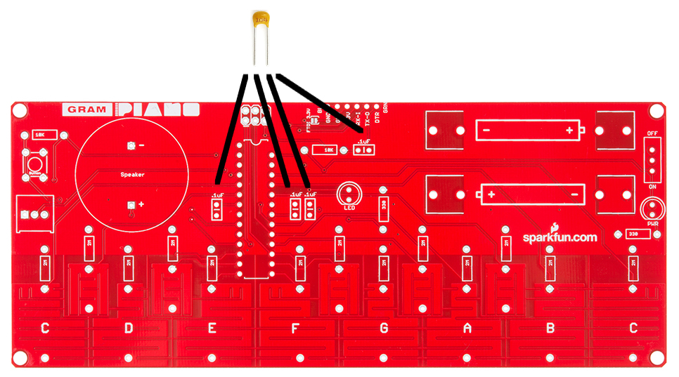
Let's start with the capacitors. Put each one into these four spots. These parts are not polarized, so don't worry about their orientation. You can use the trick of bending the legs on the under side of the board to hold the capacitors in place while you solder. After soldering a component, you can cut its legs with some diagonal cutters.
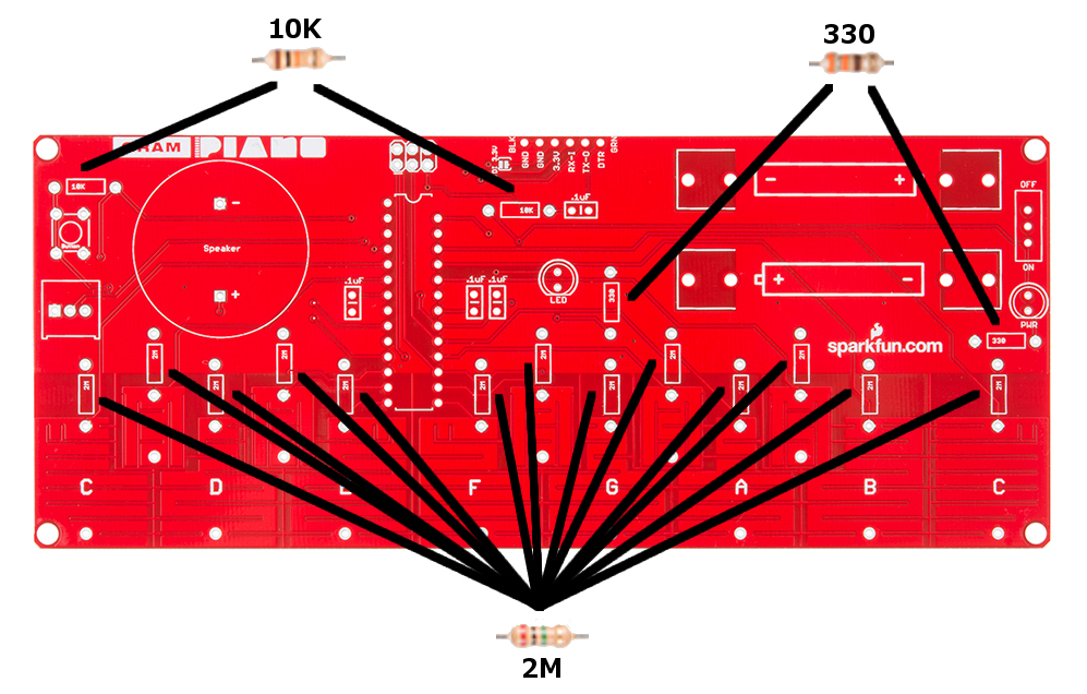
Now, let's solder in the resistors. There are three values, 2M Ohm, 10K Ohm, and 330 Ohm. Make sure you pay attention to the color rings on the resistors to ensure you put the correct value resistor in the correct spot. You can put these in one at a time, and solder each. Or, put them all in at once, and solder all at once.
Next, let's solder the medium components: the microprocessor, the switch, the pushbutton, the potentiometer, the header, and the two red LED's. The microprocessor, the LEDs, and potentiometer are all polarized, so pay extra attention when placing them on the board! The microprocessor has a semi-circle marking its polarity. Match up the half-circle on the IC to the one on the PCB. Also, the missing leg of the IC should match the missing hole in the PCB. The LEDs have a flat edge that should be matched with the flat edge on the silkscreen. The potentiometer has two notches on one side and a flat edge on the other. Match this with the silkscreen as well.
Finally, let's solder the large components: the battery clips and the PCB speaker. Both of these components are polarized. Make sure the battery clips are not put in backwards; the two open ends should be facing each other with the metal walls facing out. The PCB speaker also must go in a certain way; the plus and minus symbols on the board must match the same symbols on the speaker.

The very last step is securing the four standoffs to the board with four screws, so that the Gram Piano can sit on a flat surface and be played easily. You may need a screwdriver and/or pliers to help with this step. You can also hand tighten them. Make sure the standoffs are on the underside of the board.
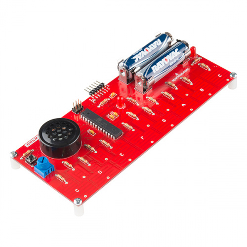
Now that the build is complete, make sure the power switch is in the OFF position, and then you can plug in the two AA batteries (in the correct orientation of course). Your kit will look just like the photo below:

Start playing with your kit now and/or read the next sections about using the default program, how it works, and how to modify the code so that you can tailor the board's functionality to your own desires.
Pre-Programmed Functionality
The microcontroller included with the Gram Piano Kit comes with a pre-installed program that lets you play with the Kit as soon as you have finished building it.
Place your built kit on a flat surface, and turn the power switch on the right side of the board into the ON position. When you power the board, the power LED (PWR) will turn on. Soon after, the center status LED in the center of the board will blink indicating the board is ready for use. Now start touching the various keys, and you will hear the corresponding notes. The board has an octave's worth of keys allowing you to play up and down a scale of notes, play simple tunes, or experiment with creating your own.
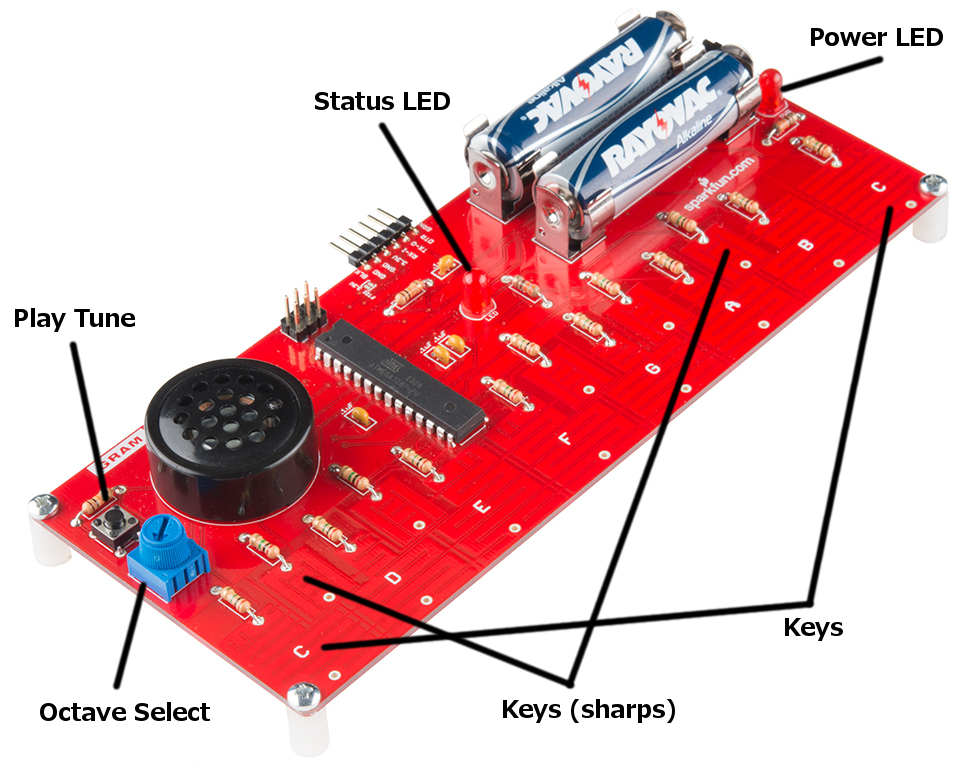
The potentiometer on the left side of the board allows you to select three different octaves. By default, the arrow should be facing up, which will tell the board to use the middle octave. If you turn the knob to the left, the keys will play notes of one octave lower. Similarly, if you turn the knob to the right, the keys will play notes one octave higher. This allows you to switch easily between three octaves without having to reprogram the board.
The button on the top left of the board is programmed to play a specific sequence of notes you may recognize. If the button is pressed again while the notes are still being played, the playing will stop.
Out of the box, the Gram Piano can essentially be used as a simple musical keyboard. In the next section, we will go over the default code running on the Gram Piano so you can learn how it works and give you ideas on how you can tailor the board to your own desires.
Code Explanation
This part of the tutorial will go over the inner workings of the pre-installed program on your Gram Piano. It will help you understand how the code works and give you ideas on how you can modify it for your own needs. The entirety of the code won't be listed here, however the full program can be found on Github. It also requires Arduino's capacitive touch library. Follow this tutorial on installing an Arduino Library if you need help with that. You will also need a FTDI Basic to program the Gram Piano using the 6 pin header on the top edge of the board.
At the top of the program, we declare the variables we need. The most important to go over are the ones below:
language:cpp
// Keyboard variables
long keys[13]; // Contains latest capacitive sense reading for each key
int threshold = 25; // Threshold for key press readings, a key plays sound if its equal to or greater than the threshold
float octave = 1.0; // Stores what octave/multiplier the key presses use, change with potentiometer

// Declaring a capactive sensor for each key on the keyboard
CapacitiveSensor CapSensors[13] =
{
  CapacitiveSensor(2,3),
  CapacitiveSensor(2,4),
  ...
  ...
The variable array keys is used to store the latest capacitive touch reading for each key on the keyboard. The higher the number for a key, the harder it's being pressed. If a particular key exceeds the threshold value (found experimentally), then the corresponding note for that key is played (unless another key takes precedence, explained later). Each time a note is played, the frequency is multiplied by the octave variable, which is set by the potentiometer. CapSensors is an array that declares a capacitive touch sensor for each of the keys. All the keys use the same send pin, but each key's pad is connected to a different pin. CapacitiveSensor(2,3) indicates 2 is the "send pin," while 3 is the pin connected to the key's pad. This particular sensor is for the low C key, and all the keys are listed in order from lowest to highest frequency. We will use each sensor in this array to detect if a key is being pressed.
Our setup() function is quite simple:
language:cpp
void setup()
{
  // Setup button pin (PB6) as input (not a default Arduino pin)
  DDRB &= ~(1 << 6); // Set bit six of the data direction register b to 0

  // Blink LED to indicate keyboard is ready for use
  pinMode(led,OUTPUT);
  digitalWrite(led,HIGH);
  delay(500);
  digitalWrite(led,LOW);
}
We initialize a button using AVR style code, since the button is not on an official Arduino digital pin. We then set the LED as an output and blink it for half a second to indicate to the user that the program is ready.
Our loop() function is where the core of the sketch lives.
language:cpp
void loop()
{
  // Measure each key press using capacitive sensing
  measureKeys();

  // Select one of three octaves based on position of potentiometer
  octave = readPot();

  // Play the note corresponding to the key press and octave
  // Higher pitch keys have priority if there were multiple presses
  playKeyPress();

  // Play melody and turn on LED if the button has been pressed
  if (buttonPressed())
  {
    digitalWrite(led,HIGH);
    playMelody();
  }
}
Each time through the loop, we first measure each key press with capacitive sensing to detect which ones are being pressed. We then check the potentiometer to select which octave of notes we will play. We then play the key press. If two or more keys are being pressed, we play the higher frequency one by default. Finally, we check if the button is pressed, and, if it is, we play a pre-programmed melody that's stored in the notes array.
Feel free to dig into the full source code to view each loop functions' implementation to understand how they work. We'll go over a few of the most important details here.
In the measureKeys() function, the most important line to understand is the following:
language:cpp
keys[i] = CapSensors[i].capacitiveSensor(5); // 5 samples per key
For each key, this takes 5 capacitive touch readings, averages them, and then stores them in our keys array. These values are then used afterward in the playKeyPress() function like this:
language:cpp
if (keys[12] > threshold)
{
    tone(spkr,NOTE_C5 * octave,30);
}
Each key is checked to see if its value is greater than the set threshold. If it is, we use Arduino's built-in tone() function to play the corresponding note for 30 milliseconds. Since the if statements check the keys from high to low pitch, higher pitch keys take priority. Only one note is ever played at a time.
The variable spkr is simply the pin to the on-board speaker. For the high C (right most note on the board), NOTE_C5 is the note/frequency to be played through the speaker by default. The variable octave can be set to .5, 1.0, or 2.0 depending on the position of the potentiometer that was read by the readPot() function. This value will be multiplied by the default NOTE_C5 value (found in pitches.h), and the speaker will play the note corresponding to the frequency just calculated.
Finally, if the push button is pressed, playMelody() is called. All this function does is go through each note stored in the array notes and plays each one for 300 milliseconds with the tone() function. After each note is played, it checks again for a button press, and the melody stops playing if a button press is detected. The LED is also turned on while the melody is playing.
These are the highlights of the core functionality of the default program. At this point, some exploring and experimenting is required to get a better grasp on the program. Always feel free to contact us if there is any confusion and we can do our best to improve the readability of the code and/or the above explanation.
Resources and Going Further
By building the Gram Piano Kit and working through this tutorial, you have learned more about soldering, capacitive touch, playing tones, and coding in Arduino. Congratulations!
For more information, check out the resources below:
From here, you can repurpose your board as you see fit. You could change the musical scale, make keys play melodies you choose or run blocks of code, or even simply just leave it as is and enjoy coming up with some simple tunes. We hope you enjoy your Gram Piano. Feel free to share with us your feedback about the kit and/or whatever creative uses you have found for it.
Looking for more resources? Check out some of these related tutorials:
- Installing the Arduino Development Environment
- Installing an Arduino Library
- Using Github
- Arduino's Capacitive Sense Library Reference
- Arduino's Tone Reference
Check out these other great audio related SparkFun tutorials: