Gator:bit Hookup Guide
This Tutorial is Retired!
Note: This tutorial is for the SparkFun gator:bit v1. If you are using any of the newer model (v2) with the barrel jack instead of JST connector, please refer to the new tutorial.
View the updated tutorial: SparkFun gator:bit v2 Hookup Guide
 LightningHawk
 Introduction
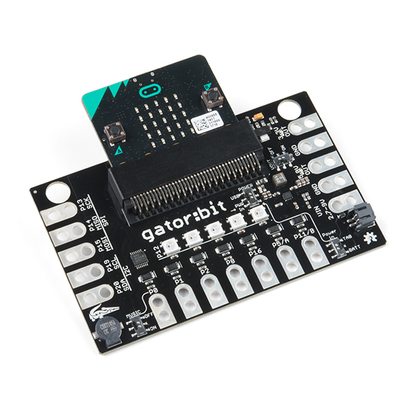
Gator:bit is a development board for BBC micro:bit. Almost every pin on the micro:bit is broken out to alligator clippable pads so you can get the most out of it. Gator:bit comes equipped with five addressable LEDs, a built-in buzzer (speaker) as well as a power management system that gives you access to 3.3V and 5V. Gator:bit can be powered from 2.7V - 9V giving you quite a range of powering options.
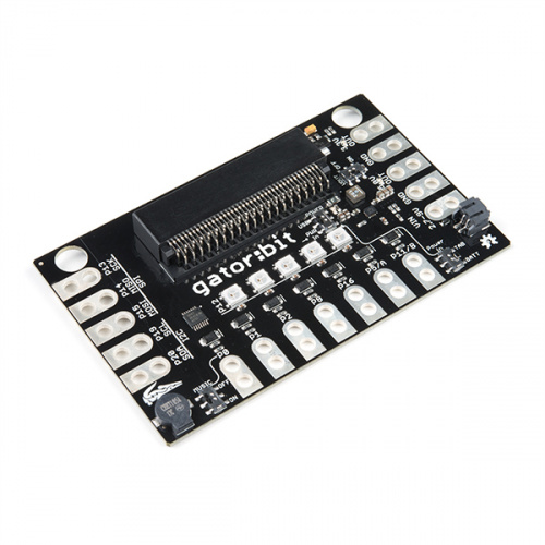
Without any external hardware Gator:bit is still an exploratory development board for micro:bit. Whether it is data visualization using the on board addressable LEDs, capacitive touch sensing on pins 0, 1, & 2, or creating musical works of art using the built-in speaker we've got it covered with the with the Gator:bit.
With some alligator clips and extra hardware you'll be able to explore inputs like sensors, potentiometers, and buttons and control outputs like lights, motors, and speakers.
Required Materials
Here are some products that will help you get started with the Gator:bit:
Suggested Materials
In addition to the above, here are some products to get you started with building circuits to control inputs and outputs using the Gator:bit:


Suggested Reading
If you aren’t familiar with the following concepts, we recommend checking out these tutorials before continuing.
What is a Circuit?
Voltage, Current, Resistance, and Ohm's Law
What is Electricity?
Light-Emitting Diodes (LEDs)
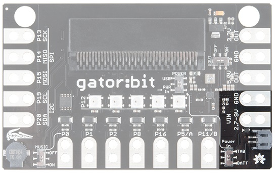
Hardware Overview
Features:
- micro:bit card edge connector
- Input voltage: 2.7V - 9V
- 5 built in addressable LEDs
- Built in buzzer
- 5V output
- 3.3V output
- 7 protected input/output pins
- 3 pins for SPI communication
- 2 pins for I2C
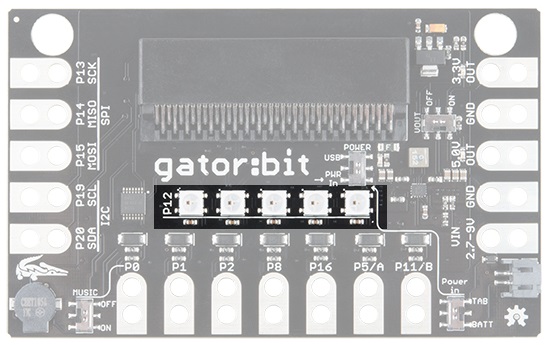
Powering Your Gator:bit
There are 2 ways of powering your gator:bit, either from the JST battery terminal or the alligator clippable pads labeled "VIN". Any voltage input between 2.7V and 9V will be regulated to 3.3V to power the micro:bit, the speaker, and for use by any of the alligator clippable pins. 5V is also regulated from the input to power the LEDs and any off-board hardware you would like to use like servo motors.
However you choose to power your boards, you must select your powering option on the switch labeled Power In on the bottom right side of the board. Choose BATT if you are using the JST terminal or select TAB if if you are using the alligator tabs with another power source. You will notice an arrow that runs from Power In to the master POWER switch near the card edge connector. If you are providing power from either the JST connector or from a clipped source that master switch should be placed down at PWR IN.
If you are not using the JST terminal or alligator clips to provide power, the gator:bit can be used with a USB on the micro:bit. If you leave the master switch set to PWR IN while using a USB cable, you will be powering the gator:bit from the micro:bit's 3.3V output. You will have full use of gator:bit with the exception of the use of the 3.3V/5V power out. If the master switch is up to USB, the voltage coming in from the micro:bit will go through the voltage regulators and give you full access to the gator:bit and any peripherals.
Input Pins
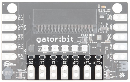
I/O Protected Pins
The point of gator:bit is to give you access to as much GPIO as possible from the micro:bit, safely. Not only are pins 0, 1, 2, 8, 16, 5 (Button A), and 11 (Button B) broken out, but they are also protected against overvoltage and overcurrent/short circuit. Pins 0, 1, & 2 are ADC pins and are also the capacitive touch pins. Pins 8, 16, 5, and 11 are digital pins capable of read and write.
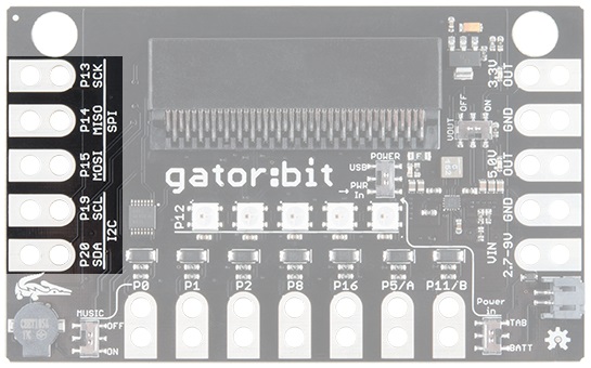
I2C and SPI Serial
The gator:bit also provides access to pins 13, 14, 15, 19 & 20. These are digital pins that can be used to read and write digital signals. Pins 13, 14, & 15 are also SPI communication pins giving you the ability to use SparkFun's SPI sensors with the gator:bit. Pins 19 & 20 are I2C communication pins which extend the use of the micro:bit to include all of SparkFun's I2C sensors.
Outputs
Voltage Output
The gator:bit gives you access to more micro:bit pins and it also gives you access to 3.3V and 5V. Your servo action is about to get a little cleaner and you'll be able to easily power peripheral hardware.
In order to use the voltage out tabs, the VOUT switch needs to be switched on. Having the option to turn it off is great when when you don't need it.
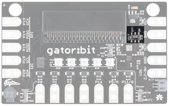
On the right side of the board there are two "OUT" pins. One for 5V and one for 3.3V. You will know when the output voltage is available because two red LEDs will turn on right above the pad. You can use either of the two ground pads since all ground is connected.

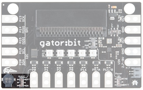
Now let's look at the fun kind of output, light and sound! On the bottom left is a buzzer. We chose a small speaker on purpose. You'll be able to explore creating digital music and then listen to it right on the gator:bit. You can easily attach a larger speaker when you are ready to show off your work.
Piezo Speaker
You'll notice another switch here. The speaker is attached to pin 0, so if you want to play music the music switch needs to be on and you won't be able to use pin 0. Conversely, if you want to use pin 0 th music switch needs to be switched off.
Addressable LEDs
LEDs! Addressable LEDs! Connected to pin 12 are 5 addressable LEDs with the first LED on the left. The Neopixel MakeCode extension is an excellent way to control these. We have a few examples using the extension coming up.
Programming Environments
There are several programming environments to use your micro:bit and gator:bit with.
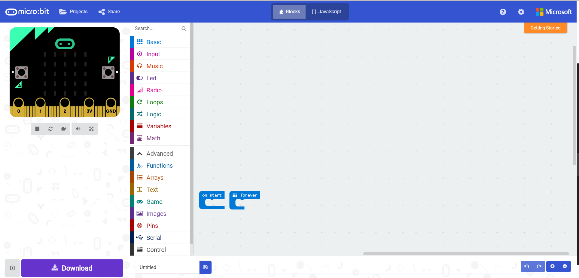
MakeCode
Makecode is a web application based on block programming. The blocks then directly convert to Javascript; you can switch back and forth for ease of inspection. To upload your program to the micro:bit you download the project and drag and drop it on the micro:bit.
A quick start guide on MakeCode is the best way to become familiar with blocks, extensions, downloading and running programs on the micro:bit.
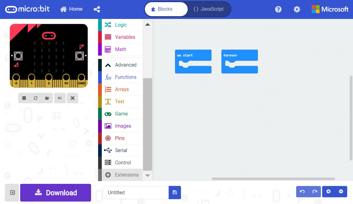
From the start you are presented with the basic building blocks on a program. on start is where your setup is, variable declarations, and any other start up messages or images. forever is your looping function. If you want to blink an LED you'd turn an LED on for some amount of time and off for some amount of time the loop would allow that to repeat forever.
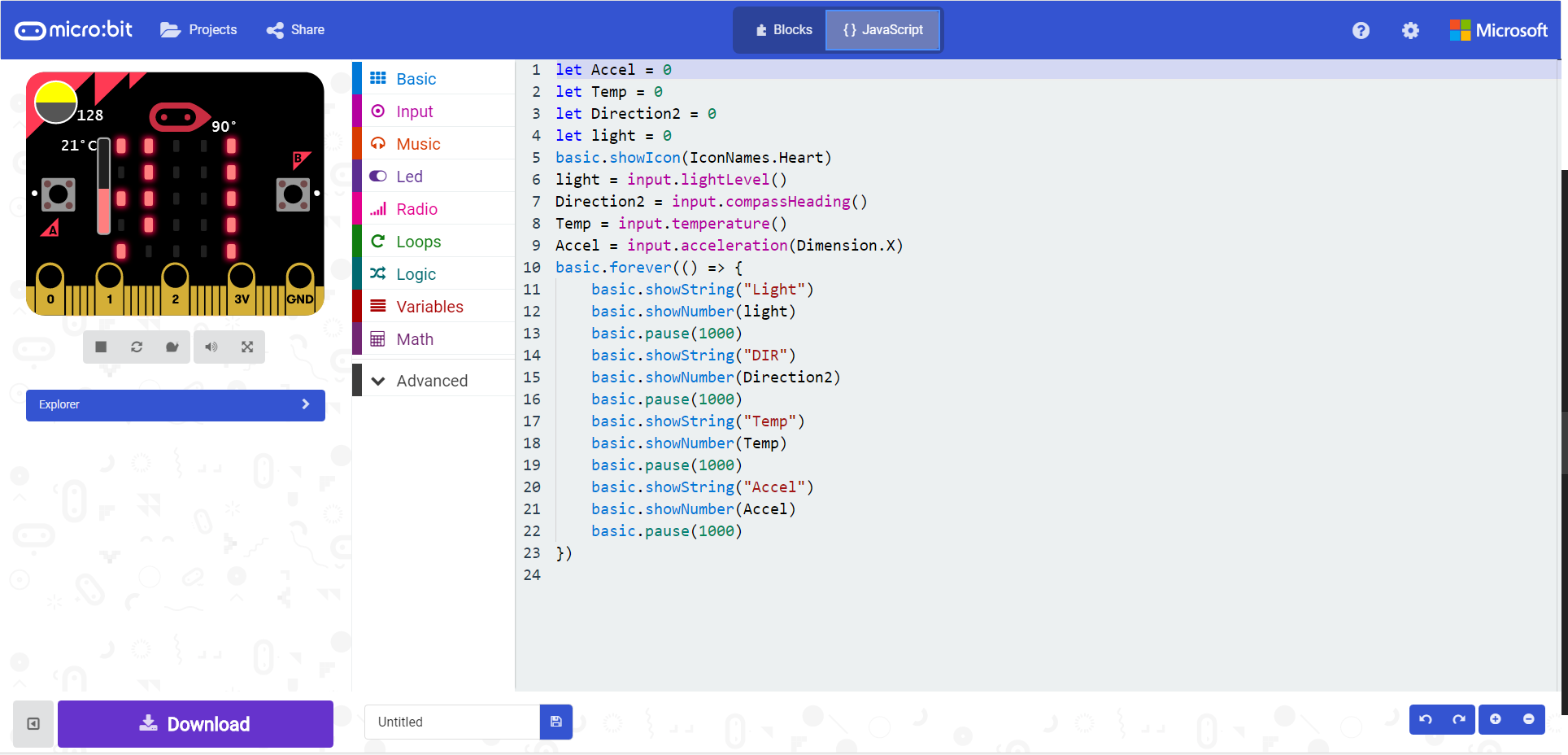
On the left hand side there is a simulation of the program with the micro:bit and the extension list. Once you've clicked on a extension list, you'll be provided with the blocks associated with that extension.

Since the blocks are based on Javascript and you can switch between looking at a program in blocks and Javascript, Makecode is a great way to start programming fast and learn another language as you go.
EduBlocks
Similar to MakeCode there is another web and block based programming environment called EduBlocks. EduBlocks translates directly to Python 3.
Using the built in sample program you can explore how to use the blocks and load the program to the micro:bit.
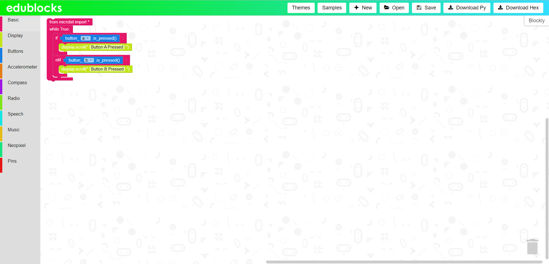
By clicking on the "Blocky" tab on the right the block code is converted to Python 3.
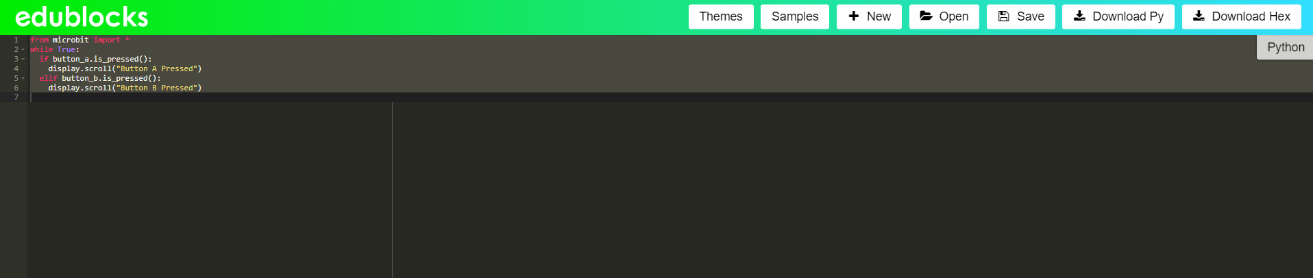
Another great way to start programming fast and learn another language as you go.
Others
micro:bit also has a Python Editor for Micropython. Micropython is a subset of Python 3 that was made specifically for microcontrollers like the micro:bit!
The micro:bit can also be programmed in Arduino. Even better, since the micro:bit has bluetooth and radio it works with a neat app called Blynk. You can create programs in Arduino then send and receive data via app. Sending data can even update the micro:bit to customize output in real time like lights.
Example Project: LED Animations
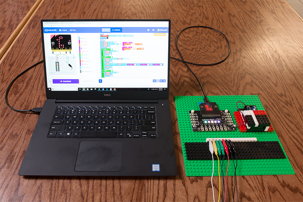
From one baseplate we've built a rack for the gator:bit, a battery enclosure, and along the bottom an alligator clip cable management system. When you are done learning all about microcontrollers, radio and bluetooth communication, and data collection and visualization, you can hang your baseplate up and keep everything organized.
Installing the NeoPixel Extension for Microsoft MakeCode
To use the addressable LEDs on the gator:bit, you will need to install a MakeCode extension. Click on Advanced -> Add Extension. Search for the neopixel extension and click on the extension to add it to your list of usable extensions.
Example
Re-create the following code into your MakeCode editor or download the example by clicking the download button to test it out!
This program starts out with a rainbow pattern across the LEDs and then turns the LEDs off sequentially from the left. Once they have all turned off, a new animation will start sequentially from the left; the LEDs will turn blue but will fill the previous LEDs with a random color rather than turning off. The brightness is turned down to 75 to save your eyes and your battery life!
Example Project: Button Melody Player
This project makes use of the speaker and buttons A and B. This project is easily extendable by using alligator clips on pins 5 (button A) and 11 (button B) to trigger the button-press event using external hardware like buttons or reed switches.

Example
Re-create the following code into your MakeCode editor or download the example by clicking the download button to test it out!
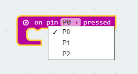
At the start of the program an eighth note is displayed on the micro:bit's 5x5 LED matrix. When button A or B is pressed a video game type melody is played. You can choose from several melodies or make one of your own. By adding a few more buttons and using the "on pin __ pressed" code block on pins 0, 1, or 2, you could create a 5 button drum machine or synthesizer!
Resources and Going Further
- gator:bit
- gator:bit GitHub Repository
- gator:bit Schematic (PDF) - Schematic for the gator:bit.
- gator:bit Eagle Files (ZIP) - Board design files for the gator:bit.
- microbit.org
- About micro:bit - Information about the micro:bit foundation.
- Hardware - Technical and compliance information.
- Getting Started - Getting started with the micro:bit.
- micro:bit Programming - List of programming environments for the micro:bit.
- Activities - Ideas from the micro:bit website.
- Projects - Projects that you can build with your micro:bit.
- Apps - The micro:bit apps let you send code to your micro:bit wirelessly using Bluetooth. No leads needed!
- Educator Teaching Resources - Resources for educators. Classroom oriented activities based on the micro:bit.
- Code Club Activities - 6 activities from Code Club to try out!
- BBC micro:bit - Kitronik University - More micro:bit tutorials.
- SparkFun micro:bit Landing Page
- SparkFun micro:bit Series - Video tutorials to get started using the micro:bit or using it with MicroPython.
For additional SparkFun tutorials, check out some of these related micro:bit tutorials:
micro:bit Educator Lab Pack Experiment Guide
How to Load MicroPython on a Microcontroller Board
Wireless Remote Control with micro:bit
SparkFun gator:log Hookup Guide
Try exploring micro:bit with cardboard circuits!