ADXL337 and ADXL377 Accelerometer Hookup Guide
 JordanDee
Introduction
The ADXL337 and the ADXL377 are both small, thin, low power, complete 3-axis accelerometers with signal conditioned analog voltage outputs.
Here are photographs of each accelerometer breakout board which we created to make these small chips easier to use:
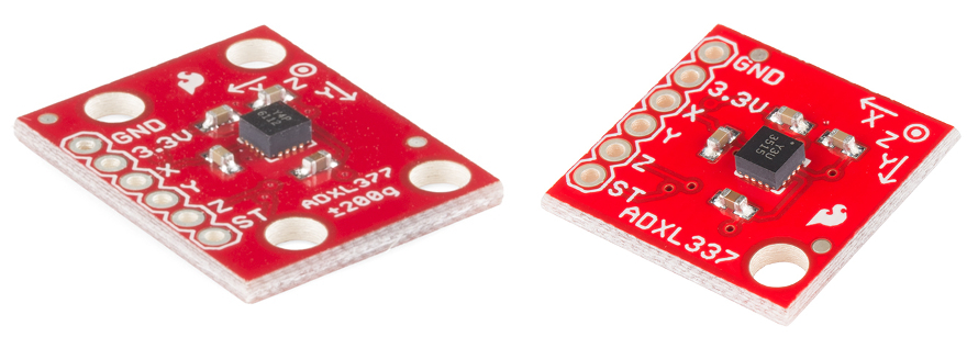
The primary difference between the two is the range of acceleration they measure. The ADXL337 measures acceleration with a full-scale range of ±3 g while the ADXL377 has a full-scale range of ±200 g for measuring more extreme changes in motion, shock or vibration.
Covered in this Tutorial
In this tutorial, we will help you learn how to use these accelerometers so you can quickly and painlessly integrate them into your project[s]. Here is what we'll cover:
- Hardware Overview -- An overview of the ADXL337/ADXL377 IC's, and their respective breakout boards we designed to make them simple to use.
- Example Hookup -- How to connect the accelerometers to the ubiquitous Arduino so we can start writing code to work with them.
- Example Code -- We've written example sketches that demonstrate how to collect sensor data as well as make sense of it.
Required Materials
- ADXL337 Breakout Board and/or ADXL377 Breakout Board
- Arduino Uno or any Arduino Board-- We will use the Uno as the example, however you should be able to use any Arduino board you have handy including the RedBoard, Pro, Mega, etc.
You may also need a breadboard, jumper wires, and straight male headers to follow the example setup, if you don't already have these or another way of connecting the Arduino to the breakout board.
Suggested Reading
Before continuing on with this tutorial, we recommend you be somewhat familiar with the concepts in these tutorials:
- Accelerometer Basics -- This is a great primer on accelerometers -- how they work, and why they're used.
- Accelerometer Buying Guide -- If you're not sure which accelerometer is best for you, check out this guide.
- Logic Levels -- The ADXL337/ADXL377 are 3.3V devices, so your analog to digital (ADC) readings will vary depending on whether you're using a 5V or 3.3V micro! Both will work, just be aware of how it affects the values the microcontroller reads.
Hardware Overview
The Breakout Boards for the ADXL337 and ADXL377 break out the all the pins you'll need to get the necessary data from the accelerometers.
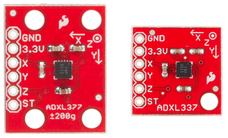
As you can see, each breakout has the same pins broken out. Here is some information about each pin:
| Pin Label | Pin Function | Input/Output | Notes |
|---|---|---|---|
| 3.3V | Power Supply | Input | Can be between 1.8 - 3.6V. |
| X | X axis acceleration | Output | Analog output whose voltage correlates to acceleration measured on the X axis |
| Y | Y axis acceleration | Output | Analog output whose voltage correlates to acceleration measured on the Y axis |
| Z | Z axis acceleration | Output | Analog output whose voltage correlates to acceleration measured on the Z axis |
| ST | Self Test | Input | Used to verify sensor functionality |
| GND | Ground | Input | 0V, common voltage to share with microcontroller circuit |
Voltage Supply Requirements
The big alert here is that the ADXL337 and ADXL377 both have a maximum voltage of 3.6V -- that range applies to both the power supply and the self test pin. You can use a 5V or 3.3V micro with these sensors as long as you power the board with 3.3V. Be aware though, that your analog to digital (ADC) readings will vary depending on whether you're using a 5V or 3.3V micro! Both will work, just be aware of how it affects the numeric values the microcontroller reads.
Fortunately, you don't need a lot of power to make the accelerometers work. In normal operating mode they typically draw about 300µA.
Extra Hardware Notes
If you are powering either the ADXL337 or ADXL377 with 3.3V, a voltage reading of 1.65V on the X pin will correspond to an acceleration reading of 0g for both chips. However, if the X pin reads 3.3V, on the ADXL337 this means a force of 3g is being applied on the x axis while the same reading on an ADXL377 would indicated a force of 200g. The usage of both chips is essentially the same, but interpreting the readings is different due to the scale that each chip measures.
The ADXL377 also has 4 mounting holes, as opposed to just two, to allow for a more secure physical connection to your project since it will likely be subjected to more extreme force.
Also, for both chips, 0.01µF capacitors are used on the X, Y, and Z outputs. This means the maximum rate you can collect acceleration data from the IC's is 500Hz.
Example Hookup
Soldering
Before you can plug your accelerometer breakout board into a breadboard and connect it to anything, you'll need to solder connectors or wires to the breakout pins. What you solder to the board depends on how you're going to use it.
If you're going to use the breakout board in a breadboard or similar 0.1"-spaced perfboard, we recommend soldering straight male headers into the pins (there are also long headers if you need).
If you're going to mount the breakout into a tight enclosure, you may want to solder wires (stranded or solid-core) directly into the pins.
Simple Hookup
This example will use an Arduino Uno to collect and interpret the sensor data from the ADXL337 or ADXL377. Since the sensors' outputs are analog, all we need are three wires between the Arduino's 'Analog In' pins and accelerometer (aside from power and ground). While the following hookup diagram shows the ADXL337, the header and connections to the Arduino are the same for both boards. Here's the hookup:
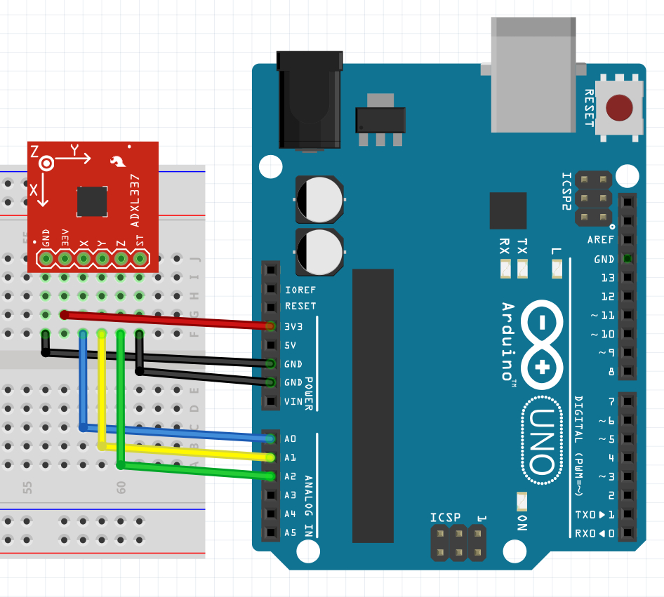
We simply have to supply the accelerometer with power (3.3V and GND), then hookup the X, Y, and Z lines of the sensor to ADC pins (A0, A1, and A2 respectively in this case). The self test pin (ST) can be left disconnected or connected to ground under normal operation. If you want to use the self test to double check the functionality of the sensor, tie it to 3.3V. Check the datasheet for more info.
Example Code
Now that your accelerometer breakout is electrically connected to your Arduino, it's time to dive into the code. The full example sketch can be found in the github repository for either the ADXL337 or the ADXL377. The code is the same with the exception of the value for the scale variable.
The first two lines of code in the sketch setup configuration variables.
language:c
int scale = 3;
boolean micro_is_5V = true;
The variable scale is set to the full scale of the accelerometer measured in g forces. It is set to 3 for the ADXL337 and set to 200 for the ADXL377, since the sensors measure a ±3g and ±200g range respectively. The variable micro_is_5V is set to true if using a 5V microcontroller such as the Arduino Uno, or false if using a 3.3V microcontroller. We want to know this because it affects the interpretation of the sensor data we will read later on.
Next we use the setup() function in initialize serial communication so that we can later print sensor data to the Serial Monitor.
language:c
void setup()
{
  // Initialize serial communication at 115200 baud
  Serial.begin(115200);
}
Using the loop() function, we collect the sensor data, scale it to the appropriate units measured in g forces, and print both the raw and scaled data to the Serial Monitor. First, let's look at how we read the sensor data.
language:c
void loop()
{
  // Get raw accelerometer data for each axis
  int rawX = analogRead(A0);
  int rawY = analogRead(A1);
  int rawZ = analogRead(A2);
We use the analog inputs A0, A1, and A2 on the Arduino and a few analog reads to get a number between 0 and 1023 that corresponds to the voltage on those pins. Those voltages reflect the latest acceleration measurement from the sensor. As an example, if the ADXL337 is measuring 3.3V on the X pin, this means it is measuring +3g's on the X axis. This in turn is measured by the microcontroller. If you're using a 3.3V microcontroller, the analog read will return 1023 and store that value in the variable rawX. If you're using a 5V microcontroller, the analog read will return 675 and store that value in that same variable instead. That's why it's important to set the variable micro_is_5V correctly so we know how to interpret these raw values.
Knowing the microcontroller's voltage, will allow us to scale these integers into readable units measured in g forces correctly. Here's how we scale these values into more meaningful units.
language:c
 float scaledX, scaledY, scaledZ; // Scaled values for each axis
  if (micro_is_5V) // microcontroller runs off 5V
  {
    scaledX = mapf(rawX, 0, 675, -scale, scale); // 3.3/5 * 1023 =~ 675
  }
  else // microcontroller runs off 3.3V
  {
    scaledX = mapf(rawX, 0, 1023, -scale, scale);
  }
We first declare the scaled variables as floats, since we want decimal places. We then check whether the microcontroller is running off of 5V or 3.3V with the boolean micro_is_5V. Based on that we scale the raw integer value of x, rawX, into a decimal value measured in g forces, called scaledX using a mapping function. We also do this for the Y and Z axis however I left those out above since they follow the exact same process. Remember that the 675 came from the fact that a 5V Arduino will measure 3.3V as 675, while a 3.3V Arduino will measure 3.3V as 1023.
The mapf() function exists in the sketch and works exactly the same as Arduino standard map() function, which you can reference here. The reason I didn't use the standard map was because it deals with integers only, and, for our purposes, we need decimal places. Thus, I essentially rewrote the exact same function using floats instead.
After scaling, we print both the raw and scaled data to the Serial Monitor. You probably only care to view the scaled data unless your debugging, however I left both there so you can compare. Here's how to print the raw and scaled data for each axis:
language:c
  // Print out raw X,Y,Z accelerometer readings
  Serial.print("X: "); Serial.println(rawX);

  // Print out scaled X,Y,Z accelerometer readings
  Serial.print("X: "); Serial.print(scaledX); Serial.println(" g");
This allows you to see the data in both forms. Afterward, we use a delay before making extra sensor reads.
language:c
delay(2000);
In the example sketch, we pause for 2 seconds (2000 milliseconds) since we are simply printing to the Serial Monitor for viewing and learning purposes. In your actual project, you can read the sensor at 500Hz at most, which means you want a minimum of 2 milliseconds in between sensor reads.
Then it's back to the beginning of loop(). Hope this helps you collect and analyze accelerometer data in your own project.
Resources and Going Further
Thanks for reading! By now you've become familiar with both the hardware and software to use the ADXL337 and ADXL377 accelerometers. We're excited to see what you build with these sensors. The following resources may be helpful for you when building your related projects:
- ADXL337 Datasheet
- ADXL377 Datasheet
- ADXL337 Breakout Github Repository
- ADXL377 Breakout Github Repository
- Using Github
Now go create something awesome with your accelerometer. Need some inspiration? Check out these other SparkFun tutorials: