Analog MEMS Microphone (VM2020) Hookup Guide
 QCPete
 bboyho
Introduction
The SparkFun Analog MEMS Microphone Breakout makes it easy to work with the Vesper VM2020 analog microphone. The VM2020 is an ultra-high Acoustic Overload Point (AOP), high dynamic range, differential analog output piezoelectric MEMS microphone. What separates this from other analog MEMS microphones is that it was designed to be used in loud environments.
Read this guide to get an overview of the breakout board and how to use it, including its technical specifications, how to hook it up to a microcontroller, and example code to get started!
Required Materials
To follow along with this tutorial, you will need the following materials at a minimum. You may not need everything though depending on what you have. Add it to your cart, read through the guide, and adjust the cart as necessary.
Arduino Microcontroller
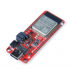
You'll want a microcontroller to power the microphone. We will be using the ESP32 WROOM.

Amplifier and Differential ADC Converter
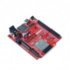
Since the analog pins on an Arduino microcontroller are usually single-ended, you will need a way to amplify the signal to a reasonable level. You will also need an differential ADC converter. We recommend using the audio codec breakout WM8960. The audio codec can amplify the signal to a reasonable level and already has input pins for a differential microphone.
Tools
Building a circuit using this breakout requires some assembly and soldering. You may already have a few of these items but if not, the tools and hardware below help with that assembly.

Prototyping Accessories
Depending on your setup, you may want to use IC hooks for a temporary connection. However, you will want to solder header pins to connect devices to the plated through holes for a secure connection. Depending on your application, you could use straight headers or right angle headers. Of course, you could also solder wire as well.


Recommended Reading
To successfully use the SparkFun MEMS microphone breakout board, you'll need to be familiar with Arduino microcontrollers, analog (aka ADC) input, and sound waves. For folks new to these topics, check out the following resources to get a feel for the concepts and verbiage used throughout this tutorial.
Installing Arduino IDE
Analog vs. Digital
IoT RedBoard ESP32 Development Board Hookup Guide
Audio Codec Breakout - WM8960 Hookup Guide
Hardware Overview
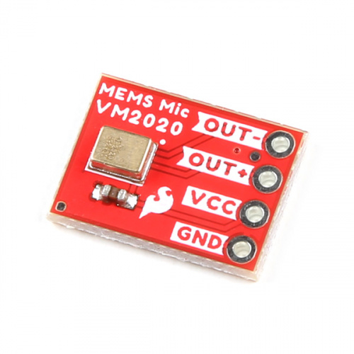
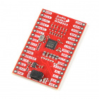
The SparkFun Analog MEMS microphone breakout board breaks out the microphone for sound detection in loud environments. Each version breaks out the VM2020 on the top side of the board.
The board receives audio input from the bottom of the board. For users soldering straight headers, you may want to consider soldering them from the back.
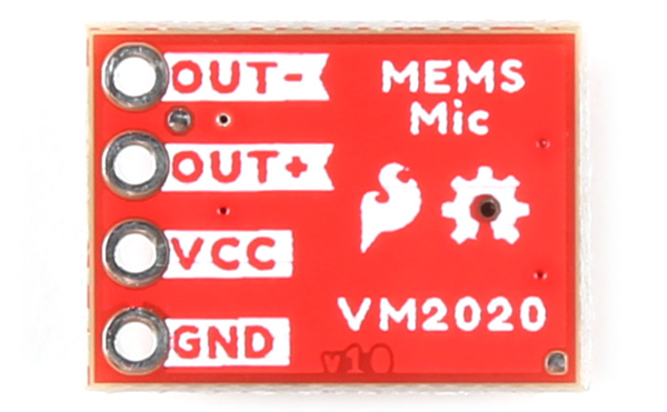
- OUT− - Audio signal output for differential −output.
- OUT+ - Audio signal output for differential +output.
- VCC - Voltage input (1.6V to 3.6V). To power this lil' mic, use a DC voltage with a supply current of about 248μA for VM2020. We'll be using 3.3V from an Arduino.
- GND - Ground.
For technically-minded folks, here are some of the features of the VM2020 and a comparison with other SparkFun MEMS Microphone Breakout boards. Make sure to check out VM2020 datasheet in the Resources & Going Further for a complete overview of the microphone.
| Electrical Characteristics | ICS-10480 | SPH8878LR5H-1 | VM2020 |
|---|---|---|---|
| High Signal-to-Noise Ratio ("SNR") | 65dbA | 67dBA | 50dbA |
| Sensitivity | about -38dBV | about -44dBV | about -63dBV |
| Flat Frequency Response | 60Hz to 20kHz | 7Hz to 36kHz | 80Hz to 10kHz |
| Low Current Consumption | <260 μA @ 3.3V | <265 µA @ 3.6V | <248 μA @ 3.6V |
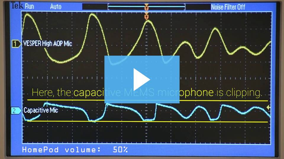
| Acoustic Overload Point (AOP) | 124 dB | 134 dB | 152 dB |
Note that the acoustic overload point of the VM2020 is greater than the other MEMS microphones. The audio is less likely to be clipped in louder settings (such as concerts, dance studios, etc.) or when the microphone is placed beside a speaker. Below is a table of typical sounds, their approximate decibel levels, and the AOP of the three microphones listed earlier. The information was gathered from a variety of sources online. Keep in mind noise-induced hearing loss varies depending on the sound intensity, the amount of exposure time, and how close your ears are to the sound source.
| Sound Source | Approximate Decibel Level [dB] | Sound Intensity | Microphone Type |
|---|---|---|---|
| Rocket Launch | 180 | Death of Hearing Tissue | |
| Shotgun Blast | 165 | ||
| Firecrackers | 150 | Reaching VM2020 AOP | |
| Jet Engine | 140 | Harmful | |
| Jackhammer | 130 | Reaching SPH8878LR5H-1 AOP | |
| Car Siren | 120 | Reaching ICS-10480 AOP | |
| Rock Concert | 115 | ||
| Lawn Mower | 90 | Risk of hearing loss when sustained levels of 90dB | |
| Loud City Traffic | 85 | Sounds above 85dB are harmful | |
| Normal Conversation | 60 | ||
| Quiet | 0 | Normal Hearing Threshold |
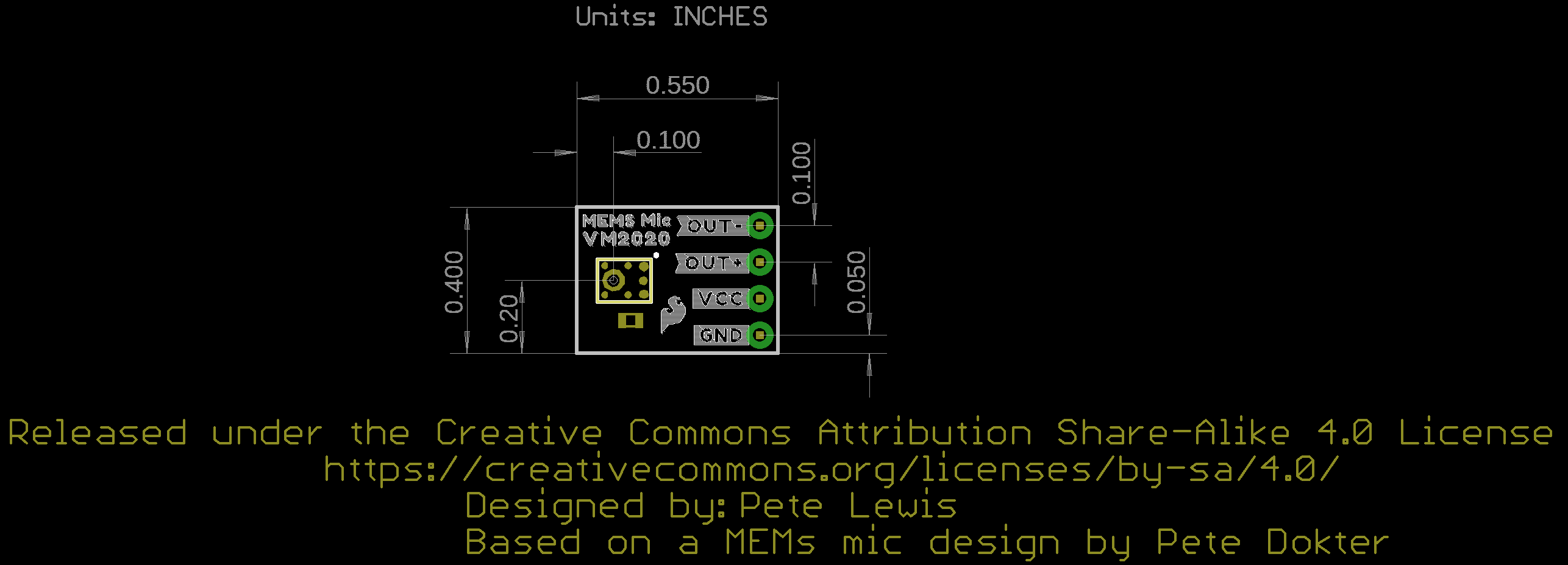
Board Dimensions
The board dimensions for the breakout are 0.40" x 0.55" (10.16mm x 13.97mm). The location of the header pins are different compared to previous versions with the extra pin for the differential output.
Hardware Hookup
Now that we're familiar with the microphone breakout, let's connect it to a microcontroller and monitor some sound!
Microphone Breakout Connections
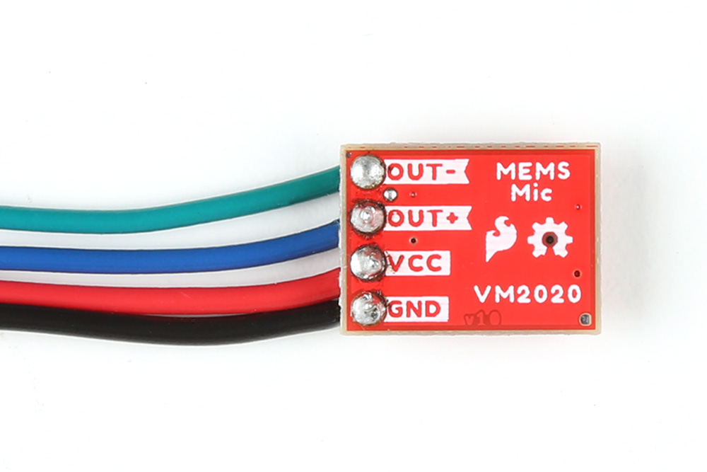
For a permanent connection, we recommend soldering four wires (or headers) to the PTHs on the breakout. We opted for soldering header pins and using jumper wires. Of course, you could also solder wires to the breakout board as well. For a temporary connection during prototyping, you can use IC hooks like these.
How to Solder: Through-Hole Soldering
September 19, 2013
We recommend soldering right angle headers. Right angle headers will provide a low height profile. This is more versatile as users can angle the microphone or add M/F jumper wires between the board and breadboard. The microphone will also sit up and away from the board.


Straight header pins being soldered to MEMS microphone.
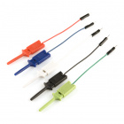
However, depending on your application, you can also solder wires to the board. We recommend using the following colors of wire to easily distinguish the signals but you can always select a different color if you prefer (or do not have the colors used available).
Right angle header pins being soldered to MEMS microphone.
- Green (or some other color not Red or Black) for Output−
- Blue (or some other color not Red or Black) for Output+
- Red for VCC
- Black for GND
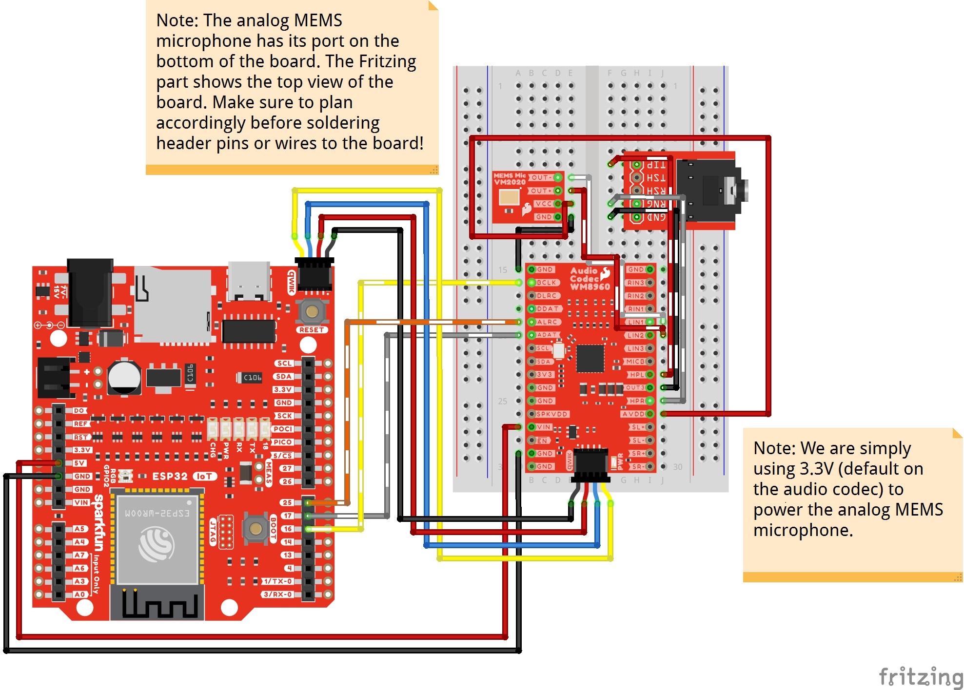
Connecting to a Microcontroller and Audio Codec WM8960
Next up we'll connect the breakout to an audio codec to amplify and read the signal. Then we will connect the boards to a microcontroller to monitor the audio signal output. For this tutorial, we used the MEMS microphone with the audio codec WM8960 and SparkFun IoT RedBoard - ESP32. The ESP32 module has I2S support and is recommended in this setup with the WM8960. Make the following connections between the breakout and IoT RedBoard - ESP32 (or whichever ESP32 variant that you choose).
| IoT RedBoard - ESP32 (or Arduino) | MEMS Microphone | WM8960 | TRS Connector |
|---|---|---|---|
| 5V | VIN | ||
| Qwiic Cable's SCL pin (or SCL) |
Qwiic Cable's SCL pin (or SCL) |
||
| Qwiic Cable's SDA pin (or SDA) |
Qwiic Cable's SDA pin (or SDA) |
||
| Qwiic Cable's 3.3V pin (or 3.3V) |
Qwiic Cable's 3.3V pin (or 3.3V) |
||
| Qwiic Cable's GND pin (or GND) |
Qwiic Cable's GND pin (or GND) |
||
| Output − | LIN1 | ||
| Output + | LIN2 | ||
| GND | GND | ||
| VCC | AVDD (i.e. 3.3V) |
||
| 25 | ALRC | ||
| 17 | ADAT | ||
| 16 | BCLK | ||
| HPL | TIP | ||
| OUT3 | GND (i.e. Sleeve) | ||
| HPR | RNG (i.e. Ring) |
The completed circuit should look something like the photo below:
Software Installation
Arduino Board Definitions and Driver
We'll assume that you installed the necessary board files and drivers for your development board. In this case, we used the IoT RedBoard - ESP32 which uses the CH340 USB-to-serial converter. If you are using a Processor Board, make sure to check out its hookup guide for your Processor Board.
Installing Board Definitions in the Arduino IDE
September 9, 2020
IoT RedBoard ESP32 Development Board Hookup Guide
August 18, 2022
How to Install CH340 Drivers
August 6, 2019
Installing the Arduino Library
We'll be using the WM8960 audio codec and connecting to the differential microphone input pins. The SparkFun Arduino library can be downloaded with the Arduino library manager by searching 'SparkFun Audio Codec Breakout WM8960' or you can grab the zip here from the GitHub repository to manually install.
Arduino Example
From the menu, select the following: File > Examples > SparkFun WM8960 Arduino Library > Example_15_VolumePlotter_MEMS_Mic_Differential. If you have not already, select your Board (in this case the SparkFun ESP32 IoT RedBoard), and associated COM port. Then hit the upload button.
Open the Arduino Serial Plotter and set it to 115200 baud to view the output. Make some noise by saying "Woooo!," clapping, or rubbing your fingers on the microphone. You should see an output showing the left input microphone's audio signal!
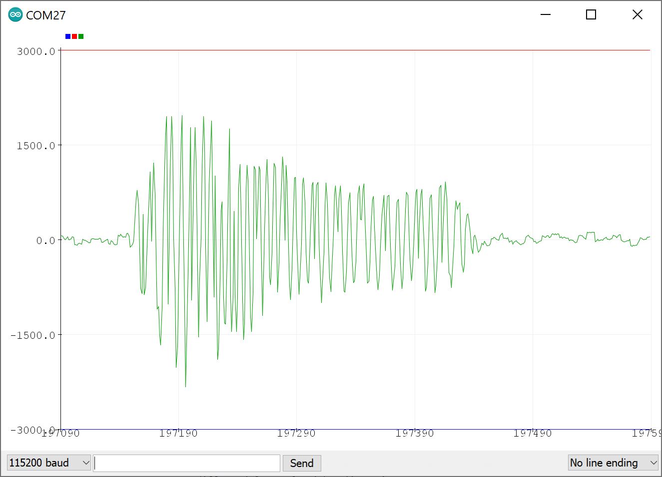
Try placing the microphone next to a loud amplified speaker and adjusting the PGA as necessary for your application. Or add a second MEMS microphone to the right channel and adjusting code to include the right channel.
if (result == ESP_OK){} statement. You will then need to calculate and plot the values as comma separated values (CSV) for the Arduino Serial Plotter to display properly. Below is how the adjusted code should look like.
  if (result == ESP_OK)
  {
    // Read I2S data buffer
    int16_t samples_read = bytesIn / 8;
    if (samples_read > 0) {
      float meanLeft = 0;
      float meanRight = 0;
      // Only looking at left signal samples in the buffer (e.g. 0,2,4,6,8...)
      // Notice in our for loop here, we are incrementing the index by 2.
      for (int16_t i = 0; i < samples_read; i += 2) {
        meanLeft += (sBuffer[i]);
      }

      // Only looking at right signal samples in the buffer (e.g. 1,2,5,7,9...)
      // Notice in our for loop here, we are incrementing the index by 2.
      for (int16_t i = 1; i < samples_read; i += 2) {
        meanRight += (sBuffer[i]);
      }

      // Average the data reading
      // Calculate left input for this example. So we must divide by
      // "half of samples read" (because it is stereo I2S audio data)
      meanLeft /= (samples_read / 2);

      // Calculate right input for this example. So we must divide by
      // "half of samples read" (because it is stereo I2S audio data)
      meanRight /= (samples_read / 2);

      // Print to serial plotter
      Serial.print(meanLeft);
      Serial.print(",");
      Serial.println(meanRight);
    }
Troubleshooting
If you need technical assistance and more information on a product that is not working as you expected, we recommend heading on over to the SparkFun Technical Assistance page for some initial troubleshooting.
If you don't find what you need there, our SparkFun Forums are a great place to find and ask for help.
Resources and Going Further
Now that you've connected your MEMS microphone breakout, it's time to incorporate it into your own project! For more information on the board, check out the resources below:
- Schematic (PDF)
- Eagle Files (ZIP)
- Board Dimensions (PNG)
- Fritzing Part (FZPZ)
- Datasheet (PDF) (VM2020)
- Application Note: Improving Barge in Performance on Smart Speakers with Ultra High Dynamic Range Microphone (PDF)
- VM2020 Compared to Capacitive MEMS Microphone in the Back Cavity of a Smart Speaker (PDF)
- WM8960 Arduino Library
- GitHub Hardware Repo
- SFE Product Showcase
Need some inspiration for your next project? Check out some of these related tutorials for ideas. Add the Analog MEMS microphone (VM2020) in your project!