Qwiic LED Stick - APA102C Hookup Guide
 El Duderino, MAKIN-STUFF
 Introduction
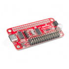
The SparkFun Qwiic LED Stick - APA102C simplifies adding addressable LED control to any I2C project using the SparkFun Qwiic System. The board includes 10 APA102 addressable LEDs controlled by an ATTiny85 on the board to work in tandem with either the SparkFun Qwiic LED Stick Arduino library or Python package..
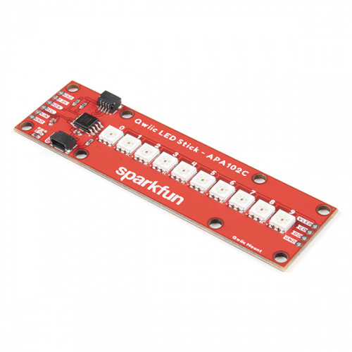
The Qwiic LED Stick was designed with making large chains of them in mind so with a quick software command, you can change the I2C address of the ATTiny85 so you can control up to 100 LEDs (10 Qwiic LED Sticks) on a single bus! Now, having a hundred LEDs in a circuit significantly increases the required current to drive them and regulators on most development boards are limited to a few hundred mA so we've designed the Qwiic LED Stick to adjust the power input so a dedicated power supply can be used to drive the LED Sticks.
In this tutorial we'll cover the hardware present on the Qwiic LED Stick, how to assemble a basic circuit and to top it off we'll take a close look at the SparkFun Qwiic LED Stick Arduino library and Python package as well as a few of the examples included in them.
Required Materials
In order to follow along with this tutorial you'll need a few items along with the Qwiic LED Stick.
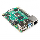
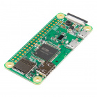
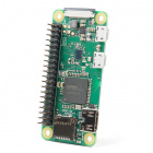
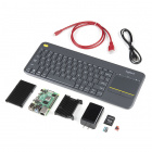
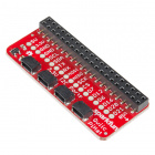
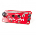
First off, the Qwiic LED Stick needs a controller like an Arduino development board or single-board computer (SBC) like a Raspberry Pi to communicate with the board. Click the button below to toggle to recommended Raspberry Pi and Qwiic Pi products.
Raspberry Pi Materials (Toggle)


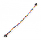
Along with a development board or SBC, you'll need at least one Qwiic cable. SparkFun carries a variety of lengths and types of Qwiic cables as seen here:


Recommended Tools
If you plan to use multiple Qwiic LED Sticks in your project, a few other tools and hardware are needed to assemble and drive your circuit. You may already have some of the products and tools suggested below so adjust your selections as needed.
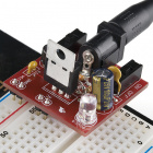
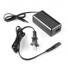
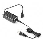
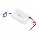
As mentioned above, using many Qwiic LED Sticks draws a significant amount of current that your microcontroller may not be able to provide. We recommend using a dedicated power supply for the APA102 LEDs on the LED Stick. Select your power supply based on the estimated total current draw of the LEDs in your circuit. Below are a few options that can work with the APA102 LEDs:
Along with a dedicated power supply, you may need some tools to solder with. If you need a soldering iron or soldering supplies, take a look at the tools and supplies below:


Recommended Reading
In case you are not familiar with the Qwiic System, we recommend reading here for an overview:
We also recommend taking a look at the following tutorials if you aren't familiar with the concepts covered in them:
Serial Terminal Basics
Hardware Overview
The Qwiic LED Stick is a fairly straightforward ATTiny85-based Qwiic board that you may be familiar with already. In this section we'll cover the hardware present on the board in detail.
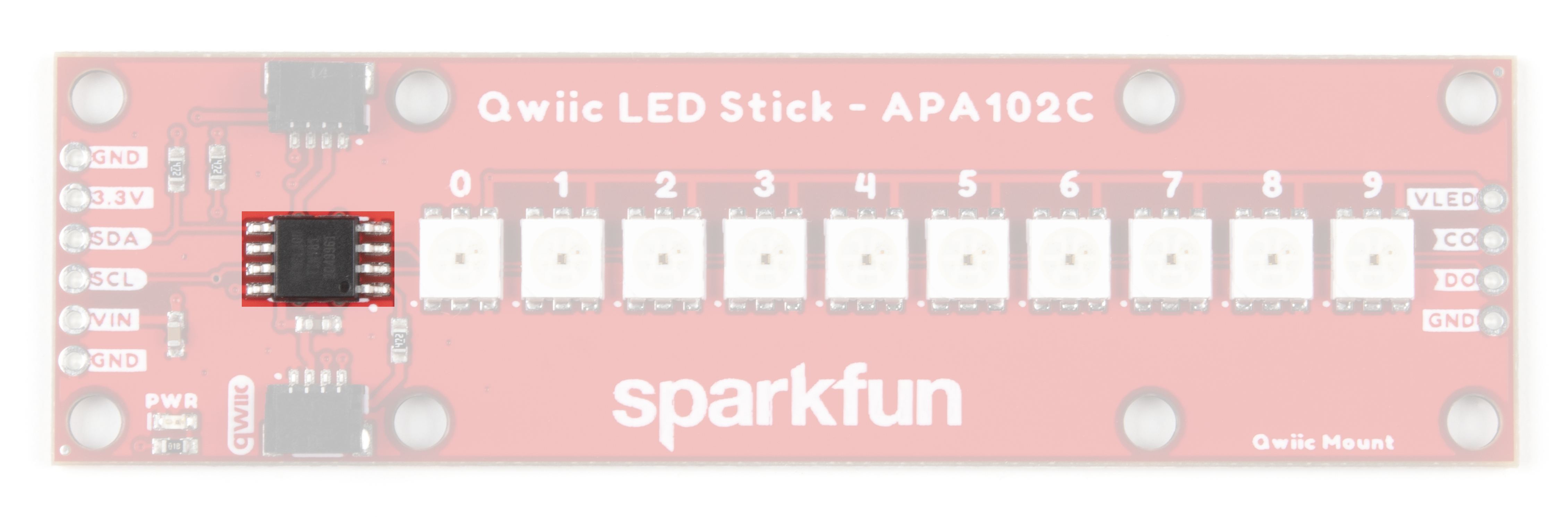
ATTiny85
The brains of the Qwiic LED Stick is one of our favorite microcontrollers, the ATTiny85. This IC comes pre-programmed with custom firmware designed to interact with the Arduino library and Python package we've written to use with this board. The ATTiny85 accepts I2C reads and writes, interprets them and outputs the appropriate strings to control any APA102 LEDs attached to it.
The default I2C address of the ATTiny85 is 0x23. Adjust the address either through the ADR jumper or via software. Read on for more information regarding changing the address in both manners.
Just like our other Qwiic breakouts using the ATTiny85, users can update or change the firmware using the 2x3 pin header on the back of the board. The firmware can be found in the Hardware GitHub Repository. For tips and tricks on how to re-program an ATTiny IC, check out this tutorial.
APA102C LEDs
The LED Stick includes 10 APA102C LEDs controlled by the aforementioned ATTiny85. APA102C LEDs operate just like most addressable LEDs over a two-wire interface. The board ties that interface to the ATTiny85 and operates both the IC and LEDs at 3.3V logic. For specific information regarding the LEDs, take a look at the APA102C Datasheet.

The board includes a dedicated power PTH pin labeled VIN (along with a spare Ground PTH) to power the LEDs directly for longer chains of Qwiic LED Sticks or circuits with an extra LED strip that require more power than a typical microcontroller can provide. Enable this power input by adjusting the VLED jumper. The APA102C LED accepts a supply voltage between 3.0V and 5.5V.
We've also routed the LED control signals out to a dedicated 0.1"-spaced PTH header on the edge of the board in case you would like to add another APA102 LED strip to the end of the LED stick. This PTH header has signal labels as well as silk labels on the bottom of the board for the coordinating wire colors (Red, Blue, Green and Yellow) to make it easy to match the wires for standard APA102 LED strips.
Qwiic and I2C Interface
As the product name suggests, the LED Stick routes the I2C interface on this board to a pair of Qwiic connectors for easy assembly using the Qwiic system. Those who prefer a a traditional soldered connection for the circuit can use the I2C pins routed to a standard 0.1"-spaced PTH header.

3.3V and GND are also provided via the Qwiic interface to power both the ATTiny85 as well as the APA102C LEDs in the default configuration.
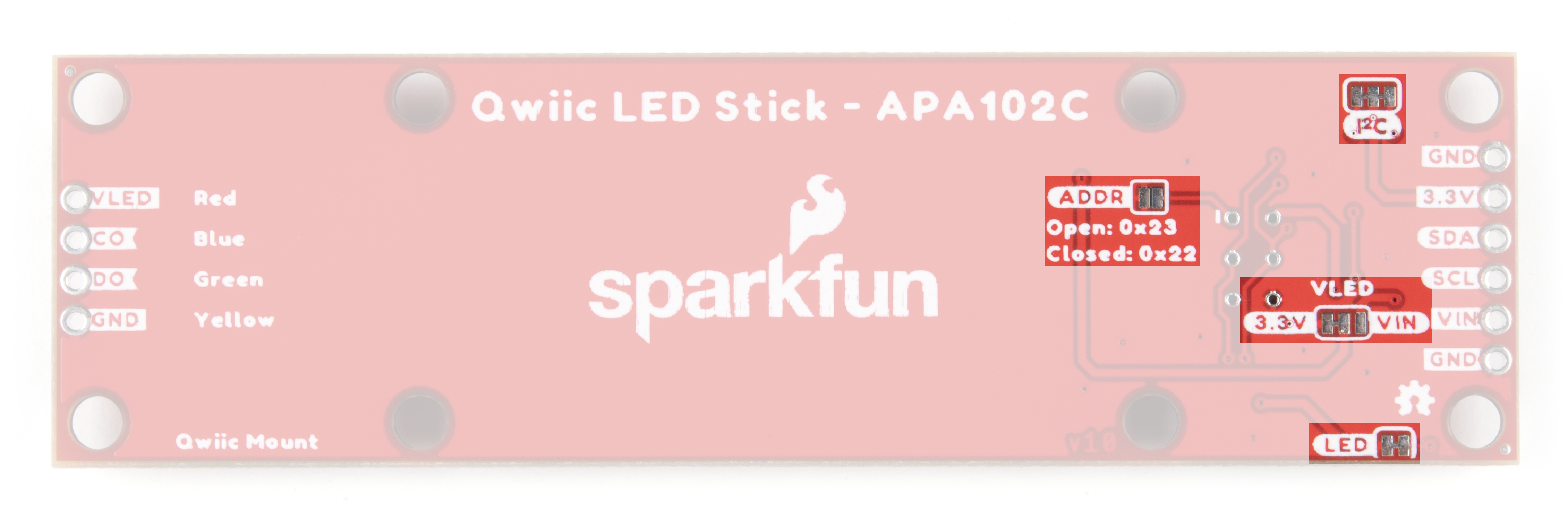
Solder Jumpers
The Qwiic LED Stick has four solder jumpers labeled I2C, VLED, ADR and LED. Let's take a closer look at them and their functionality. If you've never worked with solder jumpers before or would like a refresher, take a look at our How to Work with Jumper Pads and PCB Traces tutorial.
The I2C jumper pulls the SDA/SCL lines on the ATTiny85 to 3.3V via a pair of 4.7kΩ resistors. Disable these pull up resistors by severing the trace between the three pads. Recommended practice is to only have a single pair of pull up resistors enabled on an I2C bus to avoid communication errors caused by too strong of a parallel resistance. If you are using multiple Qwiic LED Sticks or other I2C devices in a long chain, we recommend disabling all but one of these resistor pairs.
The VLED jumper controls the input voltage for the APA102C LEDs. By default, this two-way jumper ties the APA102C VCC to 3.3V provided either over the Qwiic connector or the labeled PTH pin. For long chains of Qwiic LED Sticks, switch this jumper to the VCC side by severing the trace between the center and 3.3V pad and adding a blob of solder to connect the center pad with the VCC side. Once this is adjusted, connect a separate voltage between 3.0V and 5.5V to the VIN PTH pin to power the circuit. When in the VIN position, the board connects a 4.7µF decoupling capacitor to help smooth out power supplied to the LEDs.
The ADR jumper sets the I2C address of the ATTiny85 via a hardware adjustment and is OPEN by default. While open, the ATTiny85's address is set to 0x23. Closing this jumper adjusts the address to 0x22.
The LED jumper controls the board's power LED by tying the anode to 3.3V via a 1kΩ resistor. The jumper is CLOSED by default. Sever the trace between the two pads to disable the power LED if needed.
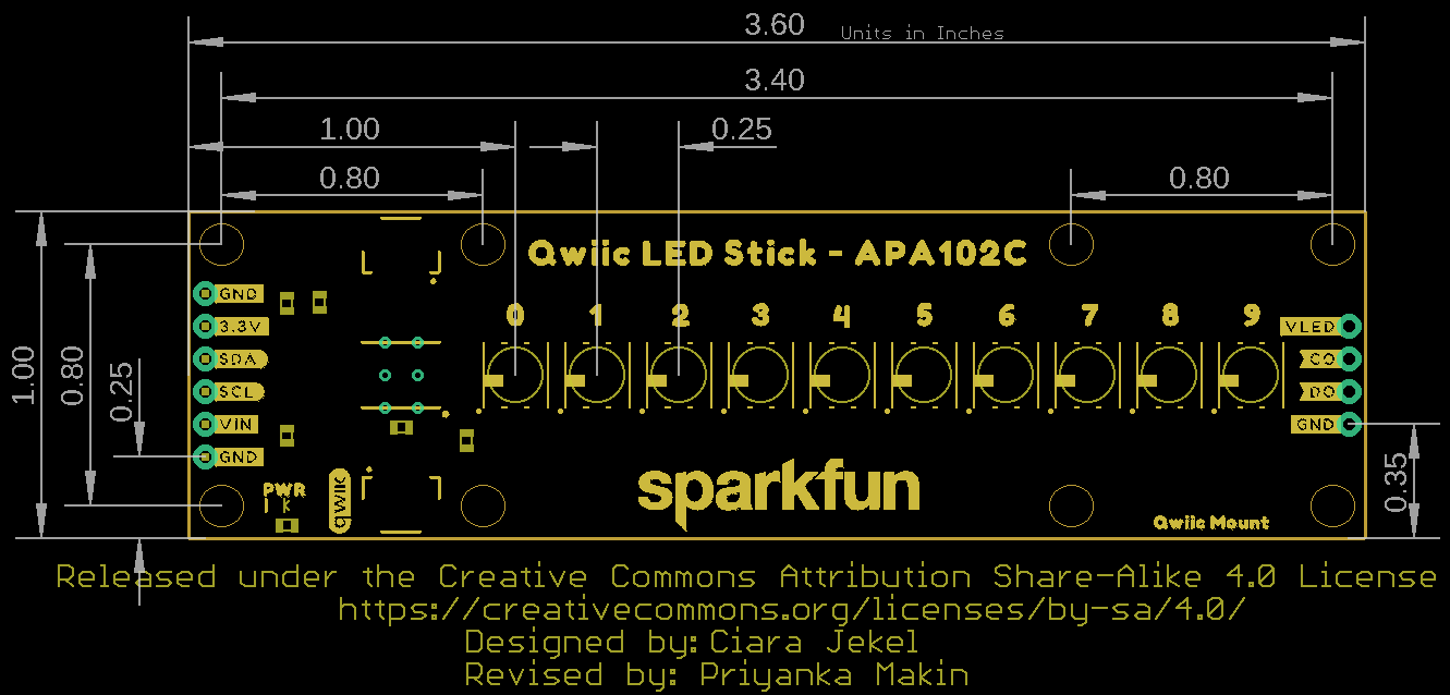
Board Dimensions
The Qwiic LED Stick measures 1.00in x 3.60in (25.4mm x 91.44mm) with four mounting holes that fit a 4-40 screw.
Hardware Assembly
Assembling a basic Qwiic LED Stick circuit is easy with the Qwiic system so we'll cover that assembly as well as a few things to be aware of when assembling a larger string of Qwiic LED Sticks or when using other APA102Cs on the end of the stick.
Basic Qwiic/I2C Assembly
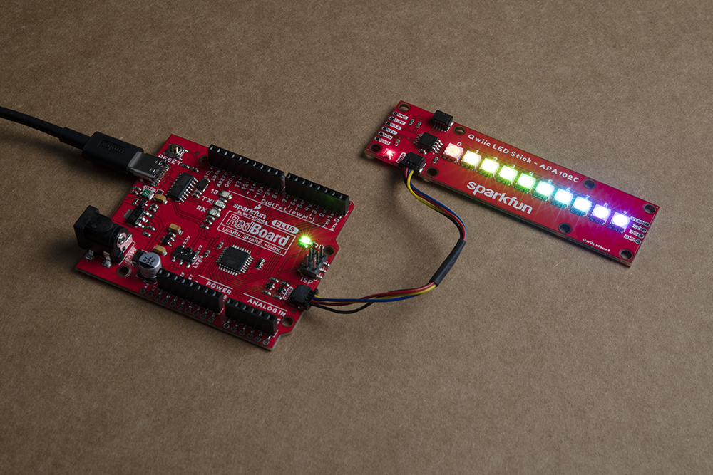
For a basic Qwiic LED Stick circuit with a board like the SparkFun RedBoard Qwiic Plus all you need to do is plug the two boards together with a Qwiic cable.
Multiple Qwiic LED Sticks and APA102C Extensions
Users who wish to use multiple Qwiic LED Sticks chained together or even with an external APA102C LED Strip connected to the LED PTH header on the side of the board will need to do some minor soldering assembly as well as adjusting solder jumpers.
First, take into account the max current draw the LED Stick chain will pull. At full power, each APA102C can draw as much as 40mA when set to white (full Red, Green and Blue) at full brightness so we recommend testing the current draw of your LED chain prior to wiring up long chains of LED Sticks (or adding an extra LED strip) to avoid damaging your controller. In our testing, while running all 10 LEDs at full brightness and White color, the strip only pulled ~65mA@3.3V so you should be safe powering a few of these from your microcontroller but note that most Qwiic development boards use a 3.3V/600mA regulator to power devices connected to the Qwiic connector.
For detailed assembly instructions and tips for building APA102 LED circuits, take a look at our APA102 Addressable LED Hookup Guide:
If using a separate power supply to power the LEDs, adjust the VLED jumper to the VIN side and connect a supply voltage between 3.0 to 5.5 to the VIN and GND pins capable of supplying enough current to power the LED chain. After making your power supply connections, plug the Qwiic LED Stick to the controller using a Qwiic cable or the I2C PTH pins.
Now that our Qwiic LED Stick circuit is assembled, let's take a look at the software packages we use to control them over I2C.
Qwiic LED Stick Arduino Library
The SparkFun Qwiic LED Stick Arduino Library makes controlling the LED stick as easy as sending the command setLEDColor() with three RGB values to set the color along with a host of other functions to control the LED Stick. Install the library by searching for "SparkFun Qwiic LED Stick" in the Arduino Library manager. Users who prefer to manually install it can get the library from the GitHub Repository or download the ZIP by clicking the button below:
Library Functions
The list below outlines all the functions available in the Qwiic LED Stick library along with quick descriptions of what they do.
Class
Construct the LED object in the global scope. The examples use LEDStick as the Qwiic LED Stick object.
LED LEDStick;
Device Setup and Settings
bool begin(uint8_t address, TwoWire &wirePort);- Initialize the LED Stick at a specified address on a chosen port. If left empty, default address will be used and Wire is used.bool isConnected();- Check if the LED Stick is connected to the port at the specified address.
LED Control
bool setLEDColor(uint8_t number, uint8_t red, uint8_t green, uint8_t blue);- Sets the color of the selected LED using RGB values between 0 and 255. If no LED is selected, all LEDs are set to the specified color. For example, to set the fourth LED to yellow the command would beLEDStick.setLEDColor(4, 0, 255, 255);.bool setLEDBrightness(uint8_t number, uint8_t brightness);- Sets the brightness of the selected LED. If no LED is selected, all LEDs are adjusted. Acceptable values are 0 to 31. Setting an LED to0will turn it off but saves the stored color value.bool LEDOff(void);- Sets all LEDs in the Qwiic LED Stick to off.bool changeAddress(uint8_t newAddress);- Change the I2C address of the ATTiny85. Enter a valid address. Note once the address is changed, the LED Stick must be initialized with the new address. For example, initialize a Qwiic LED Stick with the address 0x70 usingLEDStick.begin(0x70);.bool changeLength(uint8_t newLengths);- Change the number of LEDs in the chain. Used when adding another Qwiic LED Stick or other addressable LED strip to the circuit. Default value is 10. Max value is 100.
Arduino Examples
The Qwiic LED Stick Arduino Library includes eleven examples to get you started with the basics of the board along with some nifty lighting demos. In this section we'll look at a few of the examples and explore how they work.
Before we get into the examples, let's take a closer look at the setup used for all the examples. The code initializes both the serial and wire ports as well as starts communication with the LED Stick over I2C:
language:c
Wire.begin();
Serial.begin(115200);

if (LEDStick.begin() == false){
    Serial.println("Qwiic LED Stick failed to begin. Please check wiring and try again!);
    while(1);
}
You can open the Arduino serial monitor with the baud set to 115200 to view any serial printouts from the code. If the Qwiic LED Stick fails to initialize on the bus at the default address, the code freezes. The two most common causes of this is a bad connection between the device and controller or the Qwiic LED Stick's I2C address does not match the default value.
Example 1 - Blink
This basic example shows how to initialize the LED Stick along with controlling the LEDs on it all at once. Open the example by navigating to File > Examples > SparkFun Qwiic LED Stick Arduino Library > Example01_Blink. After opening the example, select the correct Board (in our case the SparkFun RedBoard) and Port it enumerated on. Next, click upload and barring any errors, you should see all ten LEDs set to the same color (white) and turn on and off every second.
Try adjusting the values in this line to change the color:
language:c
LEDStick.setLEDColor(50, 50, 50);
Example 3 - Single Pixels2
The third creates three arrays to set the Red, Green and Blue values for each LED. In the global class, the code creates an array for Red, Blue and Green and sets arbitrary values for each pixel.
language:c
//           Pixel#     1    2    3    4    5    6    7    8    9   10
byte redArray[10]   = {214,  78, 183, 198,  59, 134,  15, 209, 219, 186}; //r
byte greenArray[10] = { 59, 216, 170,  21, 114,  63, 226,  92, 155, 175}; //g
byte blueArray[10]  = {214, 147,  25, 124, 153, 163, 188,  33, 175, 221}; //b
After setting up the three arrays and initializing the LED Stick, the code sets the pixels to the color values to the corresponding entry in the array.
language:c
LEDStick.setLEDColor(redArray, greenArray, blueArray, 10);
For example, the fourth LED should match the color (pink/magenta) of the RGB values in the fourth entry in the array.
Example 4 - Set Brightness
The fourth example steps through all the valid brightness settings for the setLEDBrightness(); function with each LED set to a different color rainbow color (plus white) so you can get a quick idea of how each color looks at each brightness level.
Just like Example 3, the code creates three arrays for Red, Blue and Green and assigns values for each LED. After initializing the LED Stick, the main loop steps through each brightness value every second and prints out the brightness value over serial:
language:c
for (byte i = 0; i < 32; i++) {
    LEDStick.setLEDBrightness(i);
    Serial.print("Brightness level: ");
    Serial.println(i);
    delay(1000);
}
These examples round out most of the basics of the Qwiic LED Stick Library. The others include a few demos of cool effects you can do with the Qwiic LED Stick along with changing the I2C address and length of LEDs controlled when using a command not pointed at a specific LED pixel. Take a look at them either in the Arduino IDE or the Library GitHub Repository.
Qwiic LED Stick Python Package
The Qwiic LED Python package is a port of the Arduino library for users who prefer to use this board with a Raspberry Pi. The Python port includes the same eleven examples as the Arduino library to get you started from simply turning on the LEDs to creating some nifty light displays.
The package is hosted on PyPi to make installation quick and painless using simple commands in the command interface. If you prefer to manually install the package, you can find it on the GitHub repository or click the button below to download the ZIP of it:
(*Please be aware this package depends on the Qwiic I2C Driver. You can also check out the repository documentation page, hosted on Read the Docs.)
Qwiic LED Stick Py Installation
Let's go over both installation methods for the Qwiic LED Stick Python package.
Note: Don't forget to double check that the hardware I2C connection is enabled on your Raspberry Pi or other single board computer. The Raspberry Pi tutorials linked in the note above cover how to enable the Pi's I2C bus.
PyPi Installation
Hosting the package on PyPi makes installation simple on systems that support PyPi installation via pip3 (use pip for Python 2). Open a command interface and enter the following commands:
For all users (The user must have sudo privileges) privileges):
language:bash
sudo pip3 install sparkfun-qwiic-led-stick
For the current user:
language:bash
pip3 install sparkfun-qwiic-led-stick
Local Installation
Follow these instructions for a local installation. Make sure to install the setuptools package prior to installing the Qwiic LED Stick package.
Use this command for direct installation at the command line (use python for Python 2):
language:bash
python3 setup.py install
Build a package for use with pip3:
language:bash
python setup.py sdist
This command builds and places a subdirectory called "dist". Change to the new subdirectory and install the Qwiic LED Stick package using pip3 with these commands (make sure to fill in the correct version number):
language:bash
cd dist
pip3 install sparkfun_qwiic_led_stick-<version>.targ.gz
Qwiic LED Stick Python Package Operation
A complete overview of all the functions included in the Qwiic LED Stick Py is hosted on the ReadtheDocs. You can also take a look at the source code.
Upgrading the Qwiic LED Stick Python Package
In case the package is updated in the future, you may need to upgrade it. Use these commands to upgrade the package:
For all users (The user must have sudo privileges):
language:bash
sudo pip3 install --upgrade sparkfun-qwiic-led-stick
For the current user:
language:bash
pip3 install --upgrade sparkfun-qwiic-led-stick
Python Examples
The Qwiic LED Stick Python package includes eleven examples ranging from basics to get you started with the board to some some nifty demos. In this section we'll take a closer look at a few of the examples and what they do.
Just like in the Arduino library, each example creates the my_stick object and includes a begin statement that initializes the Qwiic LED Stick on the I2C bus and freezes the code if that fails:
language:python
my_stick = qwiic_led_stick.QwiicLEDStick()

if my_stick.begin() == False:
    print("\nThe Qwiic LED Stick isn't connected to the sytsem. Please check your connection", \
        file=sys.stderr)
    return
print("\nLED Stick ready!")
If your code freezes here, double check the I2C bus is enabled on your Pi and your Qwiic LED Stick is connected properly. Adjusting the address either via the ADR jumper or changing it via Example 10 - Change Address requires entering the new address in the object creation here:
language:python
my_stick = qwiic_led_stick.QwiicLEDStick(NEW ADDRESS HERE)
Example 1 - Blink
The first example demonstrates a standard "Blink" for all ten LEDs. After initializing the LED Stick on the bus, the code sets the brightness to ~50% so we don't burn our retinas looking at super-bright white LEDs.
After that, the code sets the color of the LEDs to all white and blinks them on and off every second:
language:python
my_stick.set_all_LED_color(50, 50, 50)
time.sleep(1)
my_stick.LED_off()
time.sleep(1)
Example 3 - Single Pixel 2
This example creates three lists of ten to set the Red, Green and Blue values for each LED on the stick and then uses the set_all_LED_unique_color() function to set the color of each individual LED.
Try playing around with the values in each list to switch the colors of the LEDs:
language:python
red_list = [214, 78, 183, 198, 59, 134, 15, 209, 219, 186]
green_list = [59, 216, 170, 21, 114, 63, 226, 92, 155, 175]
blue_list = [214, 147, 25, 124, 153, 163, 188, 33, 175, 221]
Example 4 - Set Brightness
The last example we'll cover here demonstrates how to set the brightness of the LED Stick. The first example uses the function in its basic form so you may be familiar with it already. This example sets the LEDs to a rainbow and steps through each valid brightness setting to give you a good idea of what each color looks like at each brightness level to figure out what works best for your project.
language:python
for i in range(0, 32):
    my_stick.set_all_LED_brightness(i)

    print("\nBrightness level: " + str(i))
    time.sleep(1)
The other examples demonstrate some neat lighting displays along with demonstrations of how to change the I2C address, adjust the total number of LEDs controlled to add other LED Sticks or LED strips.
Troubleshooting
In this section we'll outline a few troubleshooting tips for common issues you may run into using the Qwiic LED Stick.
Software Tips
Make sure when using multiple Qwiic LED Sticks to set each board to a unique I2C address. Adjust the address either by opening the ADR jumper or using the Address Examples from the Arduino library or Python package.
Also, update to the new number of LEDs in your chain using the Change Length examples in the Arduino library and Python package. Note, the default firmware limits the maximum number of LEDs to 100.
Power Supply Tips
When using many LEDs (either multiple Qwiic LED Sticks or an additional LED strip), make sure to take into account the total current draw of your LED chain. If the total current draw is outside of the limits of your chosen controller's 3.3V regulator capacity (most SparkFun Qwiic boards have a max out of 600mA@3.3V), adjust the VLED jumper to isolate the LEDs from the rest of the circuit and use a separate voltage input via the VIN PTH pin. Connect 3.3V to 5.5V power supply capable of sourcing enough current to drive the APA102 LEDs in your string.
There is no need to add a decoupling capacitor when using an external power supply connected to VIN as the board includes a 4.7µF capacitor parallel to VIN and Ground when the VLED jumper is adjusted to use that pin to power the LEDs.
General Troubleshooting
If you need technical assistance and more information on the Qwiic LED Stick or another SparkFun product that is not working as you expected, we recommend heading on over to the SparkFun Technical Assistance page for some initial troubleshooting.
If you don't find what you need there, the SparkFun Forums are a great place to find and ask for help. If this is your first visit, you'll need to create a Forum Account to search product forums and post questions.
Resources and Going Further
That wraps up this tutorial for the Qwiic LED Stick. For more information on the board, take a look at the following resources:
- Schematic (PDF)
- Eagle Files (ZIP)
- Dimensional Drawing (PNG)
- Datasheet - APA102C (PDF)
- Hardware GitHub Repository
- Qwiic LED Stick Arduino Library
- Qwiic LED Stick Python Package
- Qwiic Information Page
For some inspiration on an LED project with the Qwiic LED Stick, take a look at these tutorials:
Interactive LED Music Visualizer
LED Cloud-Connected Cloud
LuMini Ring Hookup Guide
LuMini 8x8 Matrix Hookup Guide
LumiDrive Hookup Guide
Or check out some of these blog posts for ideas: