Understanding the BC127 Bluetooth Module
 SFUptownMaker
 Introduction
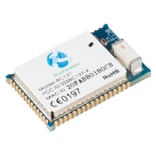
BlueCreation's BC127 Bluetooth Module is an extremely competent and easy-to-use dual-mode Bluetooth radio. It supports multiple classic mode profiles and can be used in Bluetooth 4.0 data mode. This tutorial will introduce you to the BC127 module's basic functionality, the functions and features supported by SparkFun's two BC127 support boards, and the library we've developed to support the BC127.
BC127 Breakout
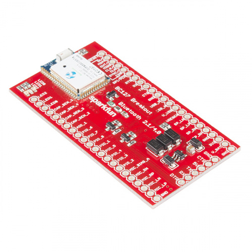
For users primarily interested in tinkering with the BC127 itself, we've created a BC127 Breakout board, which provides basic access to all the pins on the BC127 module, along with a six-pin serial header with the same pinout as the FTDI Basic boards, allowing it to connect to boards like the Arduino Pro, Pro Mini, and LilyPad. It also includes voltage regulation, serial data level shifting circuitry, and support for the built-in battery charge circuitry.
PurpleTooth Jamboree
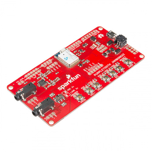
For users with a more practical project in mind, we developed the PurpleTooth Jamboree (hereafter referred to as the "PTJ"). The PTJ is a more full-function board, designed to provide audio bridge support through the A2DP, HFP, and AVRCP Bluetooth Classic profiles. It includes circuitry for converting single-ended audio inputs and microphones to balanced inputs for the module, and converting the module's balanced audio output to an amplified single-ended signal suitable for line-input and headphones. It also includes buttons for pairing and sending audio commands to remote devices, battery charge circuitry, and six-pin serial headers pinned out for connecting to either FTDI basic boards or boards like the Arduino Pro, Pro Mini, and LilyPad.
Suggested Reading
Before you go any further, please be certain that you're comfortable with the concepts covered in these tutorials:
Installing an Arduino Library
Serial Terminal Basics
BC127 Basics
On this page, we're going to lay the basic groundwork for understanding the BC127 module's functionality and capabilities. Everything we cover is in the BC127 module datasheet, but we're going to pare down what is in the datasheet to make it a bit easier to understand.
If you plan on using the BC127 with the Arduino library we provide, you may still find it useful to read through this page. While the library abstracts away the majority of the under-the-hood stuff, knowing what's going on may still be helpful, especially if you find that the library doesn't support a function you would like to use.
Operational Modes
The BC127 has two operational modes: command mode and data mode. In command mode, any data coming in on the serial port is treated as commands and will be parsed accordingly by the module's command interpreter. In data mode, any data arriving over the serial port will be directly piped out over the Bluetooth link, assuming that the module is connected to another device using the Serial Port Protocol.
Command Mode
In command mode, data received locally and appended with a carriage return (typically represented as "\r", or as 0x0D hex) will be parsed as a command. Note that the parser expects only a carriage return; if the device sending commands appends both carriage return and newline (e.g., an Arduino using the println() statement), the parser will have trouble with it. If the newline character precedes the carriage return, the parser may not accept the command at all. If the carriage return comes first, the parser will interpret the newline as a start of another command string, which can cause unexpected error messages from the module.
Throughout the rest of this guide, I will be considering the carriage return at the end of the command to be implicit. Also, while commands are theoretically case-insensitive, commands will always be presented as all-caps and I suggest that you always send all-caps strings for commands, as it sometimes makes a difference.
Finally, the parser isn't very smart about whitespace. Inserting spaces in command strings in unexpected locations will cause errors. More on this later, as we start to talk about specific commands.
Data Mode
To enter data mode, simply input the command "ENTER_DATA". The module will respond with "OK" (more on responses later), whether it is connected as an SPP device or not. From that point on, data will be tranparently passed out via the SPP connection, if one is available. If not, it will simply be ignored--it is not buffered for later delivery when a connection is available.
To exit data mode, a string of four dollar signs must be sent ("$$$$"). In order for this to be interpreted as the command to exit data mode, rather than as data to be passed, there must be a gap before the first $ and after the fourth. The length of that gap can be set by the user, but is, by default, 400ms at either end. Without that gap in place, the string will be treated as data.
Also note that data mode does not support BLE connections, despite the superficial similarity between SPP data transfer and BLE data transfer. That is a constraint of the firmware on the BC127 and may change in the future.
Commands, Responses, and Configuration Parameters
To interface with the BC127 in command mode, you need to be aware of three things: the specific commands it will accept, the responses of the module to those commands, and the various configuration parameters that the user has control over.
Commands
We're going to discuss some of the more useful commands here. For each one, we'll provide the syntax, expected responses, and a discussion of the command's actions. Reminder--terminate your command strings with a carriage return only! Extra newlines will cause an error.
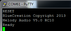
RESET - Resets the module to its currently stored default settings. You can see in the screenshot above the expected response. Note that this does not restore the factory defaults.
RESTORE - Resets the module to the factory default settings. Returns OK when complete. This restoration is only temporary, and upon a RESET the module will revert to the currently stored settings.
WRITE - Stores the current settings in non-volatile memory, to be used for configuration on next reset or power up. Returns OK when complete. Many settings require a restart of the module before they take effect; if you don't WRITE the current settings to non-volatile memory before issuing a RESET command, they'll be lost and the changes won't take effect.
Issuing RESTORE, WRITE, RESET will return the module to factory defaults and may be a good way to start out any program using the BC127, to provide a known good starting point.
GET and SET - These two commands allow for access to the configuration parameters that we'll delve into below; generally, a SET command will incur an OK response, and GET will cause the module to respond with the current value.
Responses
Any command will cause a response to be issued by the module. This will take the form of a string entirely composed of ASCII characters, terminated by both a new line ('\n' or 0x0A) and a carriage return ('\r' or 0x0D), in that order. As with commands, I'll assume that these are implicit whenever I mention a response.
All characters in all response strings will be all caps, unless the repsonse string represents received data in some way.
The two most common responses are "OK" and "ERROR". The receipt of either of these indicates that the characters entered since the last carriage return have been parsed and the input buffer is empty. For commands that take some time to execute (for example, scanning for local advertising BLE devices), many other commands cannot be submitted and will cause an "ERROR" response if submitted before the "OK" response signaling the end of the extended command is received.
Below are some of the responses the module can send in response to actions taken by the remote unit; these are naturally in addition to the responses to locally issued commands that we covered above.
CLOSE_OK SPP - The remote connection has closed the given profile. Note that SPP is just an example; that parameter can be of any type of connection, and in the event of the remote device closing all connections, you will receive one message for each profile that was connected. This can also mean that the remote device has moved out of range or been switched off.
PAIR_PENDING - A remote device is attempting to connect to the module.
PAIR_OKAY - A remote device, with the address immediately reported after the PAIR_OKAY message, has successfully paired with the BC127. Will be followed by one or more OPEN_OK messages detailing the types of connections that were established.
AVRCP_STOP, AVRCP_PLAY, AVRCP_PAUSE, AVRCP_FORWARD, AVRCP_BACKWARD - The remote AVRCP device has executed this command. Not all devices will return all of these messages upon execution of a command.
Configuration Parameters
In addtion to the commands listed above, there are numerous configuration parameters which can be set or read back using the SET and GET commands. Generally, the format for setting a value is SET PARAM=VALUE1 VALUE2 VALUE3; parameters will always have at least one parameter and may have several. When entering multiple parameters, separate subsequent parameters to the first with a space. Ther should be no whitespace between the parameter name, the equals sign, and the first value; whitespace in that region will cause an error.
It is possible to read back the current state of all configuration parameters by entering the CONFIG command; many of these values will not be cover here.
BC127 Profiles
The BC127 supports several different "profiles", which are connection types specified in the Bluetooth standard. These profiles determine the capabilities of the device and how the device responds to input.
General Connection Information
Connections between devices are managed differently when the connecting device is Bluetooth Classic or Bluetooth 4.0 (also referred to as Bluetooth Low Energy, or BLE).
Classic Mode
Here are useful commands for Classic mode connection control:
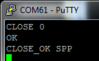
CLOSE disconnects from one of the links returned by STATUS. Pass as a parameter either a single digit corresponding to the link ID returned by STATUS or ALL, to disconnect all connections. Note that it is possible to disconnect a single profile connection but remain connected to a device with other profiles. Also note that, so long as the parameter passed is valid, this command will return OK, whether there is a connection with that link ID or not.
As you can see above, there are two responses from this command: OK, which indicates that the command was received locally successfully (i.e., no typos) and CLOSE_OK SPP, which tells you that the remote device was disconnected successfully. If there had been no connection open with link ID 0, the CLOSE_OK message would not have appeared.
DISCOVERABLE mode makes the device discoverable by other Bluetooth Classic devices in range (ON). The device will automatically switch to OFF when a connection is made; executing DISCOVERABLE ON will disconnect any existing connections.
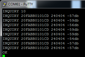
INQUIRY looks for local Bluetooth Classic devices that are discoverable. Requires an integer parameter between 1 and 48; that value determines the length of time the inquiry will last; the timeout will be equal to 1.28s times the passed value.
The response is as seen above. The INQUIRY string denotes that a device has been found. It is followed by 12 hexadecimal digits, which are the address of the device, and then six more hexadecimal digits conveying the device's capabilities. This six-digit value, the Class of Device value, is generally beyond the scope of this document. Finally, you'll see a signal strength indicator. Anything above -70db is probably strong enough to make a good connection.
Once the OK response string has been received, the inquiry process is complete.
LIST prints a list of all devices currently paired with this module, whether they are connected or not. The BC127 can store up to 8 devices in this list. Devices in this list persist through resets or power cycles even without a WRITE having been executed
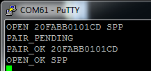
OPEN establishes a connection to a device at a given address of a given type. The above example shows a connection of type Serial Port Protocol with a device at address 20FABB0101CD. Note that all of the letters in the address and connection type must be in all caps!
The responses for this can vary. A successful connection will return the above messages: PAIR_PENDING indicates that the device was found, PAIR_OK followed by an address indicates that the pairing process completed successfully, and OPEN_OK indicates that the connection with the stated profile was successful. If there is an error in the command syntax (i.e., not enough characters for a valid Bluetooth address, or invalid profile type), the response will be ERROR. If no device at that address is found, you'll receive OPEN_ERROR. If the device is not accepting connections of the specified profile, you will get the PAIR_OK message, but you'll see the OPEN_ERROR message for the connection.
Available connection types are A2DP, AVRCP, MAP, HFP, PBAP, SPP and BLE. We'll talk about these connection types (usually referred to as "Profiles") later on in this tutorial.
RSSI returns the current link's signal strength.
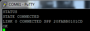
STATUS returns information about the current state of the module. As you can see above, the first line of the response is STATE followed by some information. Options here are CONNECTED, DISCOVERABLE, CONNECTABLE, or ADVERTISING. DISCOVERABLE and CONNECTABLE may both be returned at once.
If the module is CONNECTED, a list of links will follow the STATE response. Each link is given a reference ID, status, profile type, and address of connected device. In the above example, we have one connection: Link ID 0 is connected with serial port profile to a device at address 20FABB0101CD.
UNPAIR clears the list of paired devices. This does not affect the remote devices' idea of what they are paired with, however.
These are parameters which are useful for Classic connections. To change or view them, use the SET and GET commands as detailed on the previous page.
AUTOCONN=value controls the automatic connection of paired devices upon reset or power up. When value is 0, the BC127 will not attempt to connected to any previously paired devices at startup. When value is 1, the BC127 will attempt each of the paired devices (as reported by the LIST command; the number of attempts to connect to each device is set in the MAX_REC parameter. When value is 2, the BC127 will attempt to connect to a device whose address is stored in parameter REMOTE_ADDR on startup. To change this value, a WRITE RESET cycle is required.
CLASSIC_ROLE=value determines the role of the device: 0 for sink, 1 for source. This becomes important when connecting BC127 devices together for audio purposes; it determines which device sends audio and which receives.
DISCOVERABLE=value timeout sets the devices mode on startup. This is different to the DISCOVERABLE command! The command of the same name controls the immediate discoverability of the module; this sets the default state on startup.
0 makes the device undiscoverable on boot. 1 makes the device discoverable on boot, but only if it fails to autoconnect to one of its paired devices. 2 makes it immediately discoverable and overrides the autoconnect setting entirely. The value of timeout determines how long it will remain in discoverable mode before going to power save mode, in milliseconds; set that value to 0 for infinite wait.
LOCAL_ADDR=value prints the modules address to the serial port. Any attempt to change this will generate and error.
MAX_REC=value sets the number of times to attempt to reconnect to each paired device in the list of paired devices when autoconnecting. Defaults to 2 times.
REMOTE_ADDR=value provides a single address to attempt to reconnect to at startup (assuming AUTOCONN=2). The BC127 will attempt to connect MAX_REC times.
RSSI_THRESH=value puts a bottom limit to the signal strength the module will accept as a solid connection. Default is -75db.
Bluetooth 4.0 Mode
Many of those same settings and commands can be applied to Bluetooth 4.0 connections; here are the BLE-specific commands:
ADVERTISING value can be passed ON or OFF to start and stop BLE advertising. The BLE_ROLE value must be 1 for this to work; we'll discuss that later.
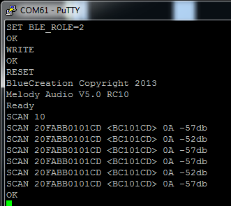
SCAN is equivalent to INQUIRY for Bluetooth 4.0 devices. Note that before executing SCAN, the module must be made into a Bluetooth 4.0 central device by setting parameter BLE_ROLE to 2, writing that value to non-volatile memory, and resetting the device.
The response is very similar to that for INQUIRY; the first field of the response is the address, the second field is the "short name" of the device, the third gives information about the device (0A indicates a general purpose dual-mode device; 02 would be a single mode device), and the fourth is the received signal strength.
SEND BLE data transmits data across the BLE link. The BLE connection does not currently support data mode; data can only be sent and received in command mode via the SEND command.
There is only one parameter associated with Bluetooth 4.0 connection only:
BLE_ROLE=value sets the type of device the BC127 will function as. SCAN can only be performed if BLE_ROLE=2; ADVERTISING will only work if BLE_ROLE=1. BLE can be disabled by setting this parameter to 0.
As we discuss individual connection protocols, we'll add more information as required for each one.
Serial Port Protocol
Most of the tinkering with Bluetooth devices in the past has focused on SPP- the Serial Port Protocol. In this mode, the device emulates a physical serial port, passing data (and, potentially, handshaking signals) across the ether as though it were a physical, wired connection.
There are several commands associated with SPP connections:
$$$$ will cause a BC127 in data mode to exit data mode and return to command mode. In order for this to work, however, there must be a guard time before the first character and after the last character; this guard time is set in paramter CMD_TO and will be discussed in the parameters section.
ENTER_DATA will put the device in data mode; any serial data coming into the serial port will be transparently forwarded to the remote device.
SEND SPP string will cause string (or whatever other data preceds the carriage return at the end of the command) to be sent over the serial connection. This allows data to be sent without entering data mode. If data is received and the module is not in data mode, the data will be prepended with RECV SPP.
There are quite a few parameters which can be set to allow for very flexible connections with the BC127 over serial:
BAUD=value sets the baud rate of the incoming and outgoing serial data. Valid values are 9600, 19200, 38400, 57600, 115200, 230400, 460800 and 921200; modules default to 9600 when set to factory defaults.
CMD_TO=value controls the guard time for detecting the $$$$ command to exit data mode. There should be a 20ms * value break in serial data before and after the $$$$ for it to be recognized; failure to respect this guard time will result in a string of four dollar signs being sent rather than causing the device to exit data mode.
ENABLE_SPP=value allows the user to selectively disable connections over SPP. Default is ON; any change in state requires a WRITE RESET to take effect.
FLOW_CTRL=value enables and disables the use of the hardware flow control pins on the BC127. Requires WRITE RESET to take effect.
PARITY=value enables and disables a parity bit for the serial data, where 1 is no parity (default), 2 is even parity, and 3 is odd parity.
SPP_TRANSPARENT=value determines whether a new SPP connection immediately activates data mode or not. OFF by default, and requires WRITE RESET for any change to take effect.
AVRCP AND A2DP Protocols
A2DP stands for Advanced Audio Distribution Profile; AVRCP is the Audio/Visual Remote Control Profile. The two are intricately related; you cannot have an AVRCP connection open without an A2DP connection open as well. You can, however, have only an A2DP connection open.
A2DP is a two-channel audio streaming protocol, which transfers data from a source to a sink. The source can be a cell phone, a media player, or the audio input on another BC127 (or similar) module. AVRCP allows the BC127 to send commands to the remote device which will cause the remote device to play, pause, stop, advance or reverse playback; some remote devices will transmit track meta data back to the BC127 via the AVRCP protocol.
The BC127 also supports the Hands-Free Protocol (HFP); we'll talk about that later, but for now be aware that incoming calls over the HFP connection will override data on the A2DP connection.
Here are the commands you'll need to know to get A2DP and AVRCP working properly:
MUSIC instruction sends a command over the AVRCP link to the A2DP source device. Valid options for instruction are PLAY, PAUSE, STOP, FORWARD and BACKWARD.
VOLUME flag has different options depending on whether the device is a sink or source (as defined by the CLASSIC_ROLE parameter discussed below). If the device is a sink, the local volume will change, but no remote volume change will occur. If the device is a source, the volume at the remote device will change. Valid values for flag are UP, DOWN, and A2DP; A2DP will report the volume level set for the A2DP speaker.
If flag is formatted as A2DP=value, that will set the volume as above to a value between 0 and 15.
These are the parameters governing A2DP/AVRCP connections:
AUDIO=value routes the A2DP audio stream from various sources/sinks. Options are 0 for analog (default), 1 for PCM Master, 2 for PCM Slave, 3 for I2S Master, 4 for I2S Slave, and 5 for SPDIF. WRITE RESET required after changes.
BPS=value sets the bits per sample for I2S and PCM codecs. Valid values are 8, 13, and 16 for PCM and 16 and 24 for I2S. WRITE RESET required after changes.
CLASSIC_ROLE=value allows user to set the device to source (1) or sink (0). This is important when attempting to make a connection between two BC127 modules, as it determines which module is expecting to send audio data and commands and which is expecting to receive. We'll cover that in an example, later. WRITE RESET required after changes.
ENABLE_A2DP=value and ENABLE_AVRCP=value allow the user to selectively enable and disable connections over A2DP and AVRCP. WRITE RESET required after changes.
I2S=value controls various parameters of the I2S system See page 15 of the BC127 manual for details on this. WRITE RESET required after changes.
INPUT_GAIN=value controls the gain level of the analog input to the device. Supports values between 0 and 15; the default value is reported as 16, although it is in fact 15.
On the next page, we'll walk through examples of interfacing the BC127 with a couple of different audio sources.
HFP and PBAP Protocols
HFP (Hands-Free Protocol) and PBAP (Phone Book Access Protocol) are implemented to support connections to cellular phones. They are related, in that most devices that support one will support both, but are not as closely related as AVRCP and A2DP.
HFP allows you to make and receive phone calls using a BC127 module. If an A2DP link is present as well as the HFP link, the HFP link will override the A2DP data stream when a call is received.
Here's a list of commands for accessing the HFP and PBAP functionality:
ANSWER accepts the incoming call on the HFP link.
CALL number initiates a call on the HFP link; if two BC127 modules are connected, this will create a bidirectional HFP link (i.e., walkie-talkie).
END hangs up an active call.
PULL_PBOOK option initiates retrieval of the phone's phonebook, call list or some subset thereof. If no option is passed, or the option PHONEBOOK is passed, the phonebook will be downloaded. For call lists, the options are OUTGOING, INCOMING, MISSED, or COMBINED. The response for each item in the list takes the following format:
PBAP_PB NAME: name
PBAP_PB TEL: number
Once all requested data has been delivered, the message PBAP_PB OK will be sent.
PULL_ABORT stops a phonebook download in progress; PBAP profile connections cannot be close during an active phonebook pull.
REJECT will cause an incoming call to be rejected.
TOGGLE_VR will activate voice recognition dialing on the phone.
TRANSFER_CALL sends audio back to the phone. This may cause the phone to drop the Bluetooth connection; that varies with phone model.
VOLUME flag allows for control of the speaker volume. Flag values UP and DOWN control speaker volume; HFP will return the current HFP speaker volume. MIC_MUTE reports the mute state of the microphone.
If the flag takes the form flag=value, the HFP volume can be adjusted independently of the A2DP stream, and MIC_MUTE=ON will mute the microphone.
There are some parameters controlling HFP and PBAP connections, as well:
ENABLE_HFP=value and ENABLE_PBAP=value can be ON or OFF to allow or disallow HFP and PBAP connections. WRITE RESET required after changes.
FORCE_ANALOG_MIC=value forces the use of the analog input in HFP even if a digital audio interface is selected. WRITE RESET required after changes.
Up Next: Usage Examples!
Now we're going to explore how to connect BC127 modules to various targets, including a cell phone, another BC127 module and a generic Bluetooth module as serial port.
Usage Examples
Here we're going to explore three use cases: connecting the BC127 to a cell phone or other media player device, streaming audio from one BC127 to another, and connecting a BC127 to another device with the SPP protocol and transmitting data between the two.
BC127 as Media Controller and Audio Output
When connected with a media playing device (I'll be using my cell phone) and the A2DP and AVRCP profiles, the BC127 can be used as an output and control device for music or other audio signals.
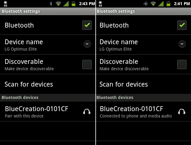
I'll start by pairing my phone with the BC127. Above you can see a couple of screenshots from my phone, showing what I see when I scan for devices, and what shows up when I've successfully connected to the BC127.
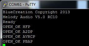
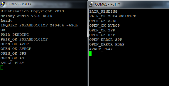
This is what the serial output on the BC127 looks like during the pairing process.
You can see that it reported a neAw connection with four profiles: Hands-Free Profile (HFP), Advanced Audio Distribution Profile (A2DP), Audio/Visual Remote Control Profile (AVRCP), and Phonebook Access Profile (PBAP). At this point, I can send commands back from the BC127 to the phone to start, stop, and pause tracks, or to advance or go back in the track list. Furthermore, the BC127 will receive messages when playback is started or stopped at the phone end. Here's an example of me starting playback on the phone, pausing it, then unpausing it via the serial terminal:
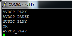
You'll note that the MUSIC PLAY command generated two responses: an OK from the BC127 indicating that the command was received and performed successfully, and an echo AVRCP_PLAY response from the phone, indicating that it successfully complied with the request. This echo response may take some time to arrive at the BC127 module, but the command executes on the phone very rapidly.
In addition to the various music control commands (see the previous page for a complete list), the BC127's various PIO pins can be used to control playback. These signals are active high; pull the pin to the module's supply voltage to send the signal.
Here's a list of functions performed by various pins:
- PIO_0 - Local volume up
- PIO_1 - Local volume down
- PIO_2 - Play/pause playback
- PIO_4 - Track backward
- PIO_5 - Track forward
The Purpletooth Jamboree board includes pins (and solderable headers) to access all of these functions.
Important note: if you receive a phone call while connected to a phone via HFP, it will interrupt your A2DP stream. If you don't have a microphone connected to the BC127, you may be unable to interact with your caller. You can disable HFP on the BC127 to prevent this; the audio output will stil be paused but the audio streams won't be transferred to the module, so you can use the speaker and mic on the phone itself.
Sending Audio from One BC127 to Another
Another great use of the BC127 is device-to-device audio. You can use this to add Bluetooth streaming to any device with an audio output to another; for example, you can stream audio across the room from your PC to a stereo amplifier without running a cord.
The process is a similar to pairing with a cell phone, as above, but requires that you pre-configure one of your BC127 modules to act as a source--they ship configured as sinks.
There are two ways to do this: with the input pins or programatically. With the input pins, simply pull the VREGEN pin high for one second (or, push the VRECEN/PAIR button on the Purpletooth Jamboree board). This will change the necessary settings, reset the board, and connect to the BC127 module with the strongest signal. Here's a screenshot of two modules undergoing this process (the source device is on the left):
You'll know the module has started its pairing process becasue the LEDs will switch off momentarily.
Also note that the audio stream won't begin until the AVRCP_PLAY command is sent. In this case, it was sent by pressing the play button on the Jamboree board; sending a MUSIC PLAY command to either module is perfectly acceptable as well.
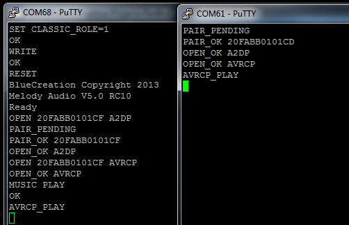
Programatically, you'll need to perform these steps:
- For best results, do a
RESTOREWRITERESETcycle on both modules, so we know what their settings are. You don't have to do this, especially if you're comfortable with the implications of any settings you've changed, but the rest of this process assumes the modules are at factory default. - On the source device (the one that has the audio input), run
SET CLASSIC_ROLE=1. This makes the device a master. This is really important--if you skip this, the connection will work and you'll get no errors, but the audio won't work. - If you want the source device to connect automatically to the sink, run
SET AUTOCONN=1. If you don't do this, you'll need to tell it to reconnect every time you reset it our power cycle it. WRITEandRESETto make those changes stick and take effect.- Connect to the other BC127 module (I'm connecting to 20FABB0101CF): 'OPEN 20FABB0101CF A2DP`.
- Issue the
MUSIC PLAYcommand on the source device. If you want remote access from the sink to starting playback, you'll need to open an AVRCP profile connection from the source to the sink (OPEN 20FABB0101CF AVRCP).
Here's a screenshot of two devices, starting in factory default, being connected up:
BC127 SPP Connection
The final use case example I'll demonstrate is connecting the BC127 as a serial device and transferring data. Here's a screen shot of two BC127 devices being connected:
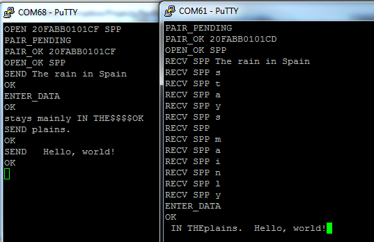
Here are the steps you'll need to perform to duplicate this demo:
- For best results, do a
RESTOREWRITERESETcycle on both modules, so we know what their settings are. You don't have to do this, especially if you're comfortable with the implications of any settings you've changed, but the rest of this process assumes the modules are at factory default. - Unlike with audio transfers, there is no source device and no sink device, here. They are both considered endpoints. That means you can initiate the connection from either end. To connect,
OPEN 20FABB0101CF SPP. - At this point, you can send data by prepending your data with
SEND. TrySEND The rain in Spain. Data is sent on carriage return (i.e., the ENTER key); this means you can't send a CR character, unless you're in data mode. - To enter data mode, use the
ENTER_DATAcommand. You can see now that data ("stays mainly") is streaming directly over the link, but that it's being received piecemeal on the right side device. After I put that device in data mode, you can see the data coming in more naturally ("IN THE"). - To exit data mode, you'll need to leave a short gap in the character stream (by default, 400ms), then enter
$$$$, then allow a short gap (again, 400ms). This will exit data mode. Note that even though I'm sending data ("plains.") in command mode, the receiving device remains in data mode and receives only the data I sent. Also note that the first space afterSENDis not transmitted, but subsequent spaces are (" Hello, world!").
Arduino Library
To make the BC127 module easy to use, we've created a library for use with Arduino and Arduino-compatible boards. We've tested it extensively under v1.0.5; we can't guarantee extensive backwards compatibility, but it should work under most post-1.0 releases.
You can download the Arduino library from our GitHub repository; the library will work for both the BC127 Breakout Board and the PurpleTooth Jamboree board.
General Concepts
The BC127 library assumes you have the BC127 connected either to a hardware or software serial port. The library should support all Atmega-based Arduino boards, and should work with any hardware or software serial port normally supported by the board.
To create an instance of the BC127 library, which will allow you to interface with the BC127 through the library's commands, you need to include the BC127 library and to invoke the class constructor for the library, like this:
language:c
#include <bc127.h>
BC127 BC127Module(&serialPortName);
You can change "BC127Module" to whatever name you're most comfortable with, of course. "serialPortName" should be replaced by the name of the serial port you have the device connected to; for example, to connect it to the main hardware serial port on an Uno or similar, your constructor would look like this:
language:c
#include <bc127.h>
BC127 BC127Module(&Serial);
If you wanted to use a software serial port, you'd need a couple of other steps: first, you'd need to include the SoftwareSerial library, and you'd need a constructor for a SoftwareSerial object:
language:c
include <bc127.h>
#include <SoftwareSerial.h>

SoftwareSerial swPort(3,2); // RX pin, TX pin
BC127 BC127Module(&swPort);
You still need to do a .begin() statement in your setup() function to set the baud rate for the serial port in question; of course, that speed must match the speed set via the BAUD parameter in the BC127 module. By default, and in all the examples here, that value is going to be 9600 baud.
Sending Commands to the Module
The BC127 library is a little different to most libraries in the way it handles data. Usually, when you call a function, the return value from that function represents the data of interest. The complexity of data from the BC127 makes that a difficult prospect; to deal with that, and with the number of different ways a command can go wrong, every command for the BC127 object returns a special value, called opResult.
There are 7 possible responses from a BC127 command function; they have names for easy reference but can also be referred to as integer values:
- REMOTE_ERROR (-5) - Most likely, there is no remote device at the address specified, or the remote device completely failed to respond.
- CONNECT_ERROR (-4) - The remote device responded, but the operation failed because of a limitation at the remote device's end.
- INVALID_PARAM (-3) - The local BC127 module didn't like something about the command it just received; perhaps there was a typographical error?
- TIMEOUT_ERROR (-2) - The command you just sent had a timeout parameter, and the BC127 failed to complete its operation in the time allotted. Most commands can timeout.
- MODULE_ERROR (-1) - The BC127 didn't like something that just happened.
- DEFAULT_ERR (0) - You should never see this.
- SUCCESS (1) - The command completed successfully.
As we proceed through the commands in the library, I'll point out the possible responses and implications thereof for each function.
There are three general-purpose commands for the module that we should talk about before we go any further: restore(), reset(), and writeConfig().
language:c
BC127Module.restore();
This command resets the module to its factory default settings. All currently set parameters will be reset to default, and any stored pairing addresses will be erased. However, this restoration will only persist until the next reset or power cycle.
language:c
BC127Module.writeConfig();
Writes the current configuration of the device into non-volatile memory; upon any reset, the module's settings will be restored to their current state.
language:c
BC127Module.reset();
Reset the module, loading the parameters that have been set in its non-volatile memory. Also closes all active connections.
Most changes to settings require that these three commands be sent, in this order, after the settings change to make the change take effect; we'll make note of whether or not that's the case for each later command.
All three of these can return "TIMEOUT_ERROR" or "SUCCESS". "TIMEOUT_ERROR" probably means the module isn't powered, isn't connected properly, or has the wrong baud rate setting.
language:c
BC127Module.connectState();
This command allows you to check on whether or not the module is currently connected to anything. It doesn't report what kinds of connections are present, just whether or not a connection is active.
It will return either "SUCCESS" or "CONNECT_ERROR". It takes a few hundred milliseconds to complete.
Note that because of buffer limitations, this will cause an overflow on the software serial buffer. It's designed to handle that gracefully but the overflow flag will still be set.
language:c
BC127Module.addressQuery(String address);
This will retrieve the current connected module's address and stick it in the String object address. Useful for identifying the module you're currently using.
"TIMEOUT_ERROR" probably means the module isn't powered, isn't connected properly, or has the wrong baud rate setting.
Making and Managing Connections
Obviously, we need to connect to other devices to make anything useful happen with this device. Here are the commands for connecting to other targets.
language:c
BC127Module.inquiry(int timeout);
This command scans the local airwaves for discoverable Bluetooth Classic devices and creates a list of up to five of them. The "timeout" parameter is the timeout in seconds times 1.3; that is, passing a "1" will result in a 1.3s timeout on the function.
It returns either the number of modules found (from 0 up to 5) or "TIMEOUT_ERROR". "TIMEOUT_ERROR" probably means the module isn't powered, isn't connected properly, or has the wrong baud rate setting.
language:c
BC127Module.getAddress(char index, String address);
Fetches the address at index in the list returned by inquiry() and puts it into a String object.
Can return either "SUCCESS" or "INVALID_PARAM"; "INVALID_PARAM" probably means you tried to index past the end of the list, or to access the list when it was, in fact, empty.
language:c
BC127Module.connect(char index, connType connection);
BC127Module.connect(String address, connType connection);
This is the actual connection command. It comes in two versions: the first simply attempts a connection to one of the devices discovered by an inquiry() call, and the second attempts a connection by address.
connType is another BC127 type; in this case your options are "SPP", "BLE", "A2DP", "AVRCP", "PBAP", and "HFP".
For the first, an "INVALID_PARAM" result indicates that you tried to connect to an index that's not present. For the second, it indicates that you sent an address with an improper number of characters.
For both of them, you can expect to see these responses:
- "MODULE_ERROR" - Address invalid (maybe not all caps, or characters that aren't hex digits).
- "CONNECT_ERROR" - Most likely, there are no devices within range that have that address.
- "REMOTE_ERROR" - We found a device with that address, but it rejected our connection for some reason (maybe it doesn't support connections of the type we requested?).
- "SUCCESS" - You're connected and ready to rock.
Using the SPP Connection
The SPP connection has a few commands associated with it.
language:c
BC127Module.setBaudRate(baudRates newSpeed);
This command changes the baud rate of the module. Your choices for parameters to pass are "s9600bps", "s19200bps", "s38400bps", "s57600bps", and "s115200bps".
Return values are a bit trickier here. The change takes place immediately--no reset required--so your serial port won't be set up right to receive the acknowledgement. You can, however, derive some useful information from the return value. If you get "SUCCESS", that means you just set the same value as the current setting. "MODULE_ERROR" indicates that something was wrong with the command, and "INVALID_PARAM" means you passed a bad value. If all went according to plan, you can expect a "TIMEOUT_ERROR".
By default, the SPP connection does not launch in data mode. Two commands are provided for entering and exiting data mode:
language:c
BC127Module.enterDataMode();
BC127Module.exitDataMode();
exitDataMode() automatically provides for the guard delay before and after the string, so you don't have to worry about it. Both can be expected to return either "SUCCESS" or "TIMEOUT_ERROR".
Once you are in data mode, data strings to and from the remote device will be simple strings, and you can treat it as a wired connection. Read and write data with the standard serial port operations for the port you bound to the module with the constructor.
Using the A2DP/AVRCP Connection
We've provided some commands for using the A2DP/AVRCP connection, as well.
language:c
BC127Module.musicCommands(audioCmds command);
This function allows you to send the commands driving the audio control to the module. Parameter options are "PLAY", "PAUSE", "FORWARD", "BACK", and "STOP" for track control, and "UP" and "DOWN" to increase or decrease the volume.
Control of the module's sink and source setting is important for audio applications; to stream audio from one module to another, you need to enable source mode, and to receive audio from another source, you need to make sure the module is in sink mode.
language:c
BC127Module.setClassicSink();
BC127Module.setClassicSource();
These two commands are pretty self-explanatory; note, though, that a writeConfig()/reset(), cycle must be performed after changing this setting.
Other Commands and Parameters
To make things easy for the advance user, we've also included three additional functions that allow you to send any command in the datasheet, and to alter or retrieve any parameter setting.
language:c
BC127Module.stdCmd(String command);
BC127Module.stdGetParam(String command, String *param);
BC127Module.stdSetParam(String command, String param);
Usage is simple; for stdCmd() simply send the string as formatted in the datasheet. The advantage here rather than using a simple serial print statement is that stdCmd() will handle error reporting for you.
For the other two, "command" should be the name of the parameter of interest, and "param" will be everything after the equal sign.
Example: SPP Connection
On this page, we'll provide an example Arduino sketch connecting two boards, each of which has a pushbutton and an LED, and pushing either button will light up both LEDs.
For simplicity's sake, we're going to write this so the code and hardware for both processors is the same.
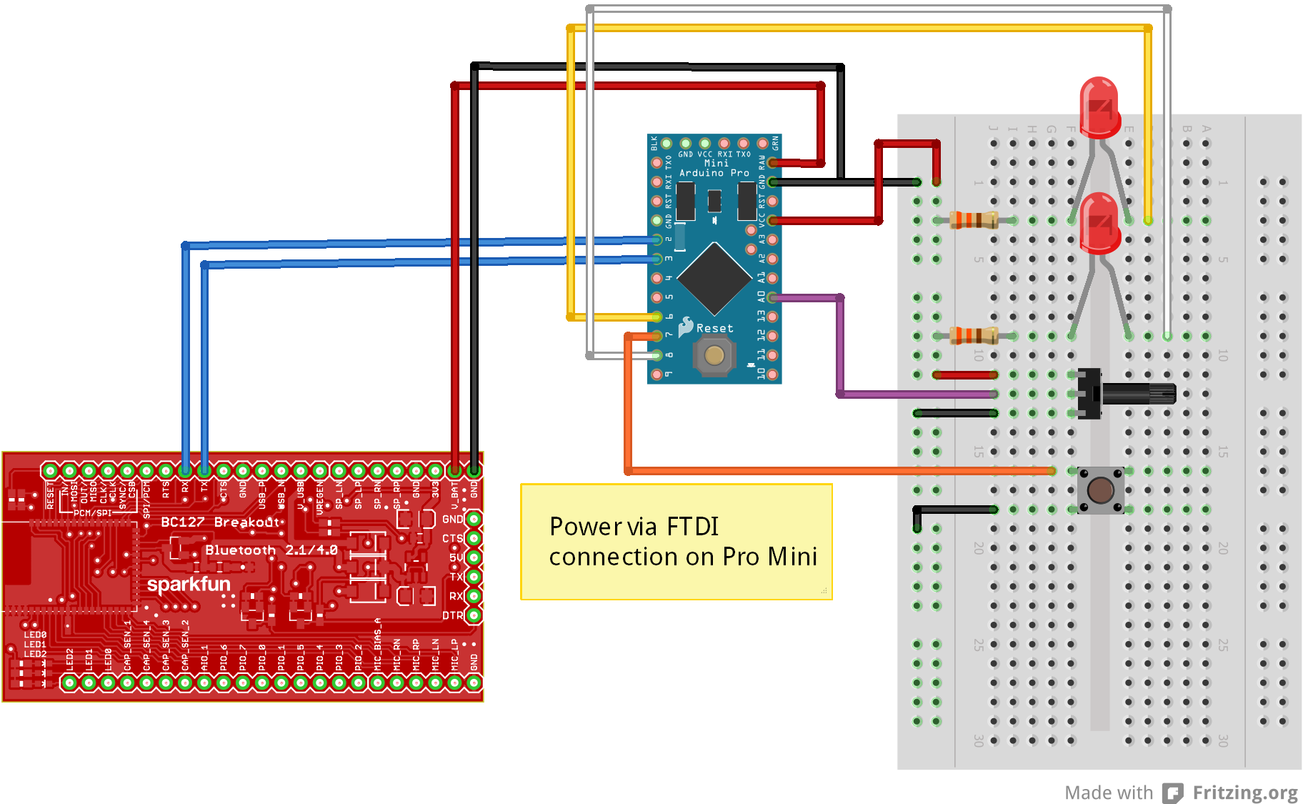
The Hardware
I'm going to keep this simple:
- two SparkFun Arduino Pro Minis
- two BC127 breakout boards
- two buttons
- two 10k linear potentiometers
- four red LEDs (with 330-ohm current limiting resistors).
As I said above, the hookup and code for the two boards will be identical.
Here's a Fritzing diagram showing the connection of one half of the setup; make two of these:
The Code
Note: This example assumes you are using the latest version of the Arduino IDE on your desktop. If this is your first time using Arduino, please review our tutorial on installing the Arduino IDE. If you have not previously installed an Arduino library, please check out our installation guide.
Everything you need to know is in the comments.
language:c
// Include the two libraries we need to use this; I'm using a software serial port
//  because time-sharing the hardware port with uploading code is a pain.
#include <bc127.h>
#include <SoftwareSerial.h>

// Create a software serial port.
SoftwareSerial swPort(3,2);  // RX, TX
// Create a BC127 and attach the software serial port to it.
BC127 BTModu(&swPort);

// Aliases for the input and output pins we're going to use.
#define POTPIN    A0
#define PWMLED    6
#define BUTTONPIN 7
#define DIGLED    8

void setup()
{
  // Serial port configuration. The software port should be at 9600 baud, as that
  //  is the default speed for the BC127.
  Serial.begin(9600);
  swPort.begin(9600);

  // Blast the existing settings of the BC127 module, so I know that the module is
  //  set to factory defaults.
  BTModu.exitDataMode(); // Just in case...do this or other commands won't take.
  BTModu.restore();
  BTModu.writeConfig();
  BTModu.reset();

  // Configure the inputs and outputs.
  pinMode(BUTTONPIN, INPUT_PULLUP);
  pinMode(DIGLED, OUTPUT);

  String buffer;  // We'll use this for capturing data from the module. I'm using
                  //  a String to make it easy to parse.

  // NB- we can assume that at this point our soft serial buffer is empty; that's
  //  all handled by the restore/write/reset cycle at the top. For other programs,
  //  your mileage may vary on this point, so it might not be a bad idea to purge
  //  the buffer before you start reading in from it.

  // Okay, first tricky bit. Since we've got the same code on both boards, we need
  //  some way to pair them. We want to wait here until the board is paired; what
  //  we'll do is wait for the button to be pressed, and then initiate pairing. We
  //  will also monitor traffic coming in from the BC127 and watch for the string
  //  "OPEN_OK SPP\n\r"; if we see that, we can bail, since we know the module
  //  is now connected. We *could* use the connectionState() function, *but* that
  //  function has such a long latency (it takes about 500ms to get a definitive
  //  answer from the module) that the chance of missing a button press is really
  //  pretty high- you'd have to hold the button for 500ms to be sure to catch it.
  while (1)
  {
    // We're going to do two things in this loop: check for a connection message,
    //  indicating that we were connected to by a remote device, and check for the
    //  button press and try to connect when we see that. Here's the connection
    //  message polling part.

    // We need to buffer our incoming serial data...
    if (swPort.available() > 0) buffer.concat((char)swPort.read());

    // ...then, we need to check if it's a full line from the serial port, and
    //  check its contents if it is.
    if (buffer.endsWith("\r"))
    {
      // If the buffer has a serial port connection message, we can break out of
      //  the while loop after entering data mode.
      if (buffer.startsWith("OPEN_OK SPP"))
      {
        BTModu.enterDataMode();
        Serial.println("Connected!");
        break;  // Exit the while loop.
      }
      buffer = "";  // Otherwise, clear the buffer and go back to waiting.
    }
    //////////////////////////////////////////////////////////////////////////////
    // Okay, this next bit is the push button polling section. Note that once the
    //  button has been pressed, it's quite a long time (10+ seconds) before we
    //  return to what we were doing above.
    if (digitalRead(BUTTONPIN) == LOW)
    {
      Serial.println("Attempting to connect...");
      if (BC127Connect() == BC127::SUCCESS)
      {
        Serial.println("Connection succeeded!");
        break;
      }
      else Serial.println("Connection failed. Back to waiting!");
    }
  }
}

// Ideally, I'd have made this a static variable and put it inside loop(), but that
//  causes Arduino to have a little hissy-fit, so I'll make it a global instead.
String inBuffer = "";

// If we've gotten to loop(), we can assume that we're connected to the remote
//  device. We're going to pass a packet back and forth that looks like this:
//     xy\r
//  x  - 8-bit value for the brightness of the dimmable LED.
//  y  - 0x00 or 0x01 for whether the remote button is pressed or not.
//  \r - end of string value. \r is not a valid data byte, so it makes a good
//       check on complete packet receipt.
void loop()
{
  // These are the variables we need to get this job done. By making them static,
  //  they only get initialized once and persist through loop calls.

  static byte outBuffer[3];
  static int ledVal = 0;
  static boolean buttonVal = false;
  static unsigned long lastLoop = millis();

  // This first bit is where we handle the receipt of characters from the remote
  //  device. We'll handle our data collection and sending later.

  // Add to the buffer one character at a time...
  if (swPort.available() > 0) inBuffer.concat((char)swPort.read());
  // ...then check to see if we've received an end-of-packet character...
  if (inBuffer.endsWith("\r"))
  {
    // ... and parse the packet if we have.
    ledVal = (int)inBuffer[0]; // This is a pre-linearized value from the pot on the
                               //  other board.
    digitalWrite(DIGLED, (int)inBuffer[1] ? LOW : HIGH); // This is the other board's
              //  button state. We want to invert it, of course, so a received 1
              //  (indicating the other button is high/unpressed) results in a low
              //  for this board's LED.
    inBuffer = "";  // Clear the buffer.
  }

  analogWrite(PWMLED, ledVal);

  // Our standard "loop without delay" method.
  if (lastLoop + 50 < millis())
  {
    lastLoop = millis();
    outBuffer[0] = (byte)(linearizeLED(analogRead(POTPIN)));
    outBuffer[1] = (boolean)digitalRead(BUTTONPIN);
    outBuffer[2] = '\r';
    swPort.write(outBuffer[0]);
    swPort.write(outBuffer[1]);
    swPort.write(outBuffer[2]);
  }
}

// Sweet little function that takes a potentiometer's input and turns it into a
//  PWM values that will appear, to a user, to be a linear brightness increase
//  across the range of the potentiometer.
int linearizeLED(int potVal)
{
  int PWMArray[] = {0, 1, 2, 3, 5, 7, 9, 12, 16, 20, 25, 31, 38, 46, 54, 64, 75, 87,
                      100, 114, 130, 147, 165, 185, 207, 230, 255};
  byte index = map(potVal, 0, 1024, 0, 26);
  return PWMArray[index];
}

// Useful function which identifies a local BC127 module and connects to it.
int BC127Connect()
{
  int connectionResult = BC127::REMOTE_ERROR; // Our return value. Assume failure.
  BTModu.inquiry(10);   // Spend 13 seconds seeking local devices.
  String address;   // Buffer for addresses we've found.
  // This loop will scan through the addresses found (there will be a maximum of
  //  five) and identify any BC127 modules (their addresses all start with "20FABB").
  for (byte i = 0; i < 5; i++)
  {
    // If there IS an address at index i...
    if (BTModu.getAddress(i, address))
    {
      // ...check to see if it's a BC127 and if it IS...
      if (address.startsWith("20FABB"))
      {
        // ...attempt to connect to it...
        connectionResult = BTModu.connect(address, BC127::SPP);
        break; // ...and quit looking at the rest of the addresses.
      }
    }
  }
  // Okay, hopefully, by now we've found and connected to a BC127. If not, return
  //  an error...
  if (connectionResult != BC127::SUCCESS) return connectionResult;
  // ...but, if so, we want to try to enter data mode.
  else connectionResult = BTModu.enterDataMode();
  return connectionResult;
}
Example: Audio Bridge
This example is for a pair of BC127 modules, one of which is set up as a receiver and the other as a transmitter. The transmitter module will automatically pair to the receiver and start streaming audio from its input.
Pete uses this in his office to send audio from his computer to his stereo on the other side of the room.
One thing to note, if you implement this yourself: it takes some time (~2 minutes) for one of the devices to notice that the remote has disappeared, reset, and retry the connection. That can't really be rushed; it's inherent to the BC127 module. A possible way around it would be to pair with an SPP connection and reset if you miss a heartbeat signal; I'll leave that as an exercise for the reader. After all, the fun is in the hacking!
The Hardware
The hardware is identical at both ends: an Arduino Pro Mini 3.3V hooked up to a Purpletooh Jamboree. Here's a Fritzing diagram showing how it works:

Power is a delicate thing, here. For best results, you probably want to power the transmitter using the on-board microUSB connector with some kind of power supply external to the signal source; say, a cell phone charger or wall wart. If you are using this to transmit a signal from a PC, powering it from the onboard USB can set up ground loops which will cause a noticeable hum or hiss in the signal.
The Receiver
Note: This example assumes you are using the latest version of the Arduino IDE on your desktop. If this is your first time using Arduino, please review our tutorial on installing the Arduino IDE. If you have not previously installed an Arduino library, please check out our installation guide.
The receiver end uses the Pro Mini to monitor the connection and restart the module if the connection is lost. The reason for this is simple: when a paired module loses its connection, it only wants to restore a connection with the paired device. However, if the paired device loses its knowledge of the pairing, the connection can't be restored until the receiver gets reset. Hence, the Pro Mini.
We also need to issue the AVRCP "PLAY" command across the link, to start the audio flowing. The Pro Mini handles that, as well.
The code comments give you all the deets about how this is done. Here's the code:
language:c
// Include the two libraries we need to use this; I'm using a software serial port
//  because time-sharing the hardware port with uploading code is a pain.
#include <bc127.h>
#include <SoftwareSerial.h>

// Create a software serial port.
SoftwareSerial swPort(11,10);  // RX, TX
// Create a BC127 and attach the software serial port to it.
BC127 BTModu(&swPort);

void setup()
{
  // Serial port configuration. The software port should be at 9600 baud, as that
  //  is the default speed for the BC127.
  Serial.begin(9600);
  swPort.begin(9600);
}

// buffer *should* be a static within loop(), but Arduino freaks out about that,
//  so I'm making it a global. Le sigh.
String buffer = "";

void loop()
{
  // resetFlag tracks the state of the module. When true, the module is reset and
  //  ready to receive a connection. When false, the module either has an active
  //  connection or has lost its connection; checking connectionState() will verify
  //  which of those conditions we're in.
  static boolean resetFlag = false;

  // This is where we determine the state of the module. If resetFlag is false, and
  //  we have a CONNECT_ERROR, we need to restart the module to clear its pairing
  //  list so it can accept another connection.
  if (BTModu.connectionState() == BC127::CONNECT_ERROR  && !resetFlag)
  {
    Serial.println("Connection lost! Resetting...");
    // Blast the existing settings of the BC127 module, so I know that the module is
    //  set to factory defaults...
    BTModu.restore();

    // ...but, before I restart, I need to set the device to be a SINK, so it will
    //  enable its audio output and dump the audio to the output.
    BTModu.setClassicSink();

    // Write, reset, to commit and effect the change to a source.
    BTModu.writeConfig();
    // Repeat the connection process if we've lost our connection.
    BTModu.reset();
    // Change the resetFlag, so we know we've restored the module to a usable state.
    resetFlag = true;
  }
  // If we ARE connected, we'll issue the "PLAY" command. Note that issuing this when
  //  we are already playing doesn't hurt anything.
  else BTModu.musicCommands(BC127::PLAY);

  // We want to look for a connection to be made to the module; once a connection
  //  has been made, we can clear the resetFlag.
  if (BTModu.connectionState() == BC127::SUCCESS) resetFlag = false;
}
The Transmitter
Note: This example assumes you are using the latest version of the Arduino IDE on your desktop. If this is your first time using Arduino, please review our tutorial on installing the Arduino IDE. If you have not previously installed an Arduino library, please check out our installation guide.
As with the receiver, we want to watch for a failure in the connection, then reconnect.
Check out the code:
language:c
// Include the two libraries we need to use this; I'm using a software serial port
//  because time-sharing the hardware port with uploading code is a pain.
#include <bc127.h>
#include <SoftwareSerial.h>

// Create a software serial port.
SoftwareSerial swPort(11,10);  // RX, TX
// Create a BC127 and attach the software serial port to it.
BC127 BTModu(&swPort);

String address = "20FABB0101CF"; // Remote module's address. If I were an optimist,
                                 //  I'd scan for BC127 modules and treat any one I
                                 //  found as the remote. Let's hard code for safety.

void setup()
{
  // Serial port configuration. The software port should be at 9600 baud, as that
  //  is the default speed for the BC127.
  Serial.begin(9600);
  swPort.begin(9600);
}

void loop()
{
  // Loop doesn't have to do much...just monitor the connection and try and restore
  //  it if it's lost.
  if (BTModu.connectionState() == BC127::CONNECT_ERROR)
  {
    // Blast the existing settings of the BC127 module, so I know that the module is
    //  set to factory defaults...
    BTModu.restore();

    // ...but, before I restart, I need to set the device to be a SOURCE, so it will
    //  enable its audio input and forward the data to the remote.
    BTModu.setClassicSource();

    // Write, reset, to commit and effect the change to a source.
    BTModu.writeConfig();
    BTModu.reset();

    // Now, attempt to connect. There are timeouts on these operations, so we won't
    //  sit forever.
    BTModu.connect(address, BC127::A2DP);
    BTModu.connect(address, BC127::AVRCP);
    // If we DID connect, we want to use the "PLAY" command to start the devices
    //  streaming audio. If we didn't, well, who cares? No harm in a spurious "PLAY".
    BTModu.musicCommands(BC127::PLAY);
  }
}
Resources and Going Further
For more information on the BC127 module, check out these documents:
- SparkFun Bluetooth Audio Breakout - BC127
- SparkFun Purpletooth Jamboree - BC127 Development Board
- Module Datasheet
- Melody v5.0 Manual- this is the complete reference for the commands and behavior of the firmware that ships with the BC127 modules we sell
- Melody v5.2 Manual- this is a pre-release and unsupported version of the firmware which neither we nor BlueCreation will offer support for. If you update your module's firmware to this (which we will not tell you how to do), you're on your own!
- GitHub Code Repo: Arduino Library
For more tutorial action, check out these related links: