SIK Experiment Guide for Arduino - V3.3
This Tutorial is Retired!
View the updated tutorial: SparkFun Inventor's Kit Experiment Guide - v4.0
 HelloTechie,
  Toni_K
Experiment 6: Reading a Photoresistor
Introduction
In experiment 2, you got to use a potentiometer, which varies resistance based on the twisting of a knob. In this circuit, you’ll be using a photoresistor, which changes resistance based on how much light the sensor receives. Since the RedBoard and Arduino Uno R3 can’t directly interpret resistance (rather, it reads voltage), we need to use a voltage divider to use our photoresistor. This voltage divider will output a high voltage when it is getting a lot of light and a low voltage when little or no light is present.
Parts Needed
You will need the following parts:
- 1x RedBoard + USB mini-B Cable or Arduino Uno R3 + USB A-to-B Cable
- 1x Breadboard
1x LED - 1x 330Ω Resistor
- 6x Jumper Wires
- 1x Photoresistor
- 2x 10k Resistors
Hardware Hookup
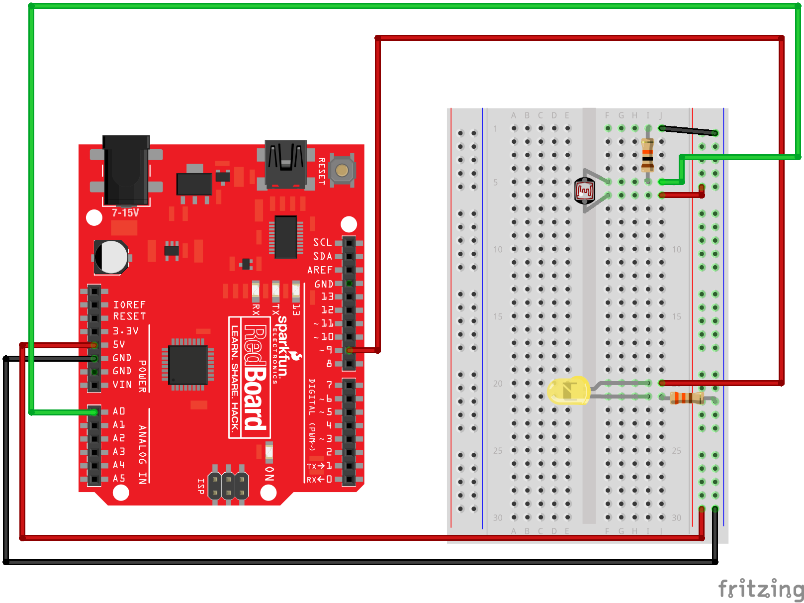
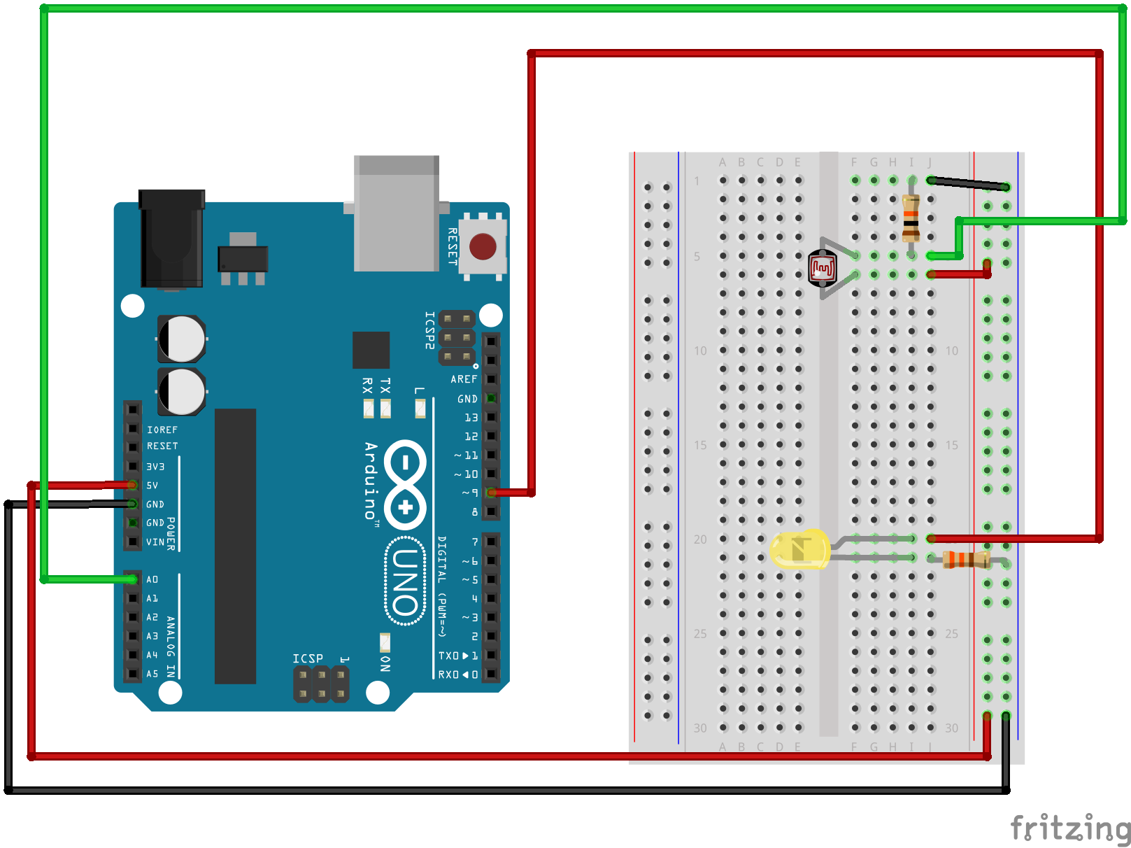
Ready to start hooking everything up? Check out the Fritzing diagram below, to see how everything is connected.
| Polarized Components | Pay special attention to the component’s markings indicating how to place it on the breadboard. Polarized components can only be connected to a circuit in one direction. |
Fritzing Diagram for RedBoard
Fritzing Diagram for Arduino
Open the Sketch
Open Up the Arduino IDE software on your computer. Coding in the Arduino language will control your circuit. Open the code for Circuit 06 by accessing the “SIK Guide Code” you downloaded and placed into your “Examples” folder earlier.
To open the code go to: File > examples > SIK Guide Code > SIK_circuit06_photoResistor
You can also copy and paste the following code into the Arduino IDE. Hit upload, and see what happens!
language:cpp
/******************************************************************
 * SparkFun Inventor's Kit
 * Example sketch 06
 *
 * PHOTO RESISTOR
 *
 * Use a photoresistor (light sensor) to control the brightness
 * of a LED.
 *
 * This sketch was written by SparkFun Electronics,
 * with lots of help from the Arduino community.
 * This code is completely free for any use.
 * Visit http://learn.sparkfun.com/products/2 for SIK information.
 * Visit http://www.arduino.cc to learn about the Arduino.
 *
 * Version 2.0 6/2012 MDG
 * Version 2.1 9/2014 BCH
/*****************************************************************/

// As usual, we'll create constants to name the pins we're using.
// This will make it easier to follow the code below.

const int sensorPin = 0;
const int ledPin = 9;

// We'll also set up some global variables for the light level:
int lightLevel;
int calibratedlightLevel; // used to store the scaled / calibrated lightLevel
int maxThreshold = 0;     // used for setting the "max" light level
int minThreshold = 1023;   // used for setting the "min" light level

void setup()
{
  pinMode(ledPin, OUTPUT);    // Set up the LED pin to be an output.
  Serial.begin(9600);
}

void loop()
{
  lightLevel = analogRead(sensorPin);  // reads the voltage on the sensorPin
  Serial.print(lightLevel);
  //autoRange();  // autoRanges the min / max values you see in your room.

  calibratedlightLevel = map(lightLevel, 0, 1023, 0, 255);  // scale the lightLevel from 0 - 1023 range to 0 - 255 range.
                                                  // the map() function applies a linear scale / offset.
                                                  // map(inputValue, fromMin, fromMax, toMin, toMax);
  Serial.print("\t");         // tab character
  Serial.print(calibratedlightLevel);   // println prints an CRLF at the end (creates a new line after)

  analogWrite(ledPin, calibratedlightLevel);    // set the led level based on the input lightLevel.
}
/******************************************************************
 * void autoRange()
 *
 * This function sets a minThreshold and maxThreshold value for the
 * light levels in your setting. Move your hand / light source / etc
 * so that your light sensor sees a full range of values. This will
 * "autoCalibrate" to your range of input values.
/*****************************************************************/

void autoRange()
{
  if (lightLevel < minThreshold)  // minThreshold was initialized to 1023 -- so, if it's less, reset the threshold level.
    minThreshold = lightLevel;

  if (lightLevel > maxThreshold)  // maxThreshold was initialized to 0 -- so, if it's bigger, reset the threshold level.
    maxThreshold = lightLevel;

  // Once we have the highest and lowest values, we can stick them
  // directly into the map() function.
  //
  // This function must run a few times to get a good range of bright and dark values in order to work.

  lightLevel = map(lightLevel, minThreshold, maxThreshold, 0, 255);
  lightLevel = constrain(lightLevel, 0, 255);
}
Code To Note
lightLevel = map(lightLevel, 0, 1023, 0, 255);
Parameters
map(value, fromLow, fromHigh, toLow, toHigh)
value: the number to map
fromLow: the lower bound of the value's current range
fromHigh: the upper bound of the value's current range
toLow: the lower bound of the value's target range
toHigh: the upper bound of the value's target range
When we read an analog signal using analogRead(), it will be a number from 0 to 1023. But when we want to drive a PWM pin using analogWrite(), it wants a number from 0 to 255. We can "squeeze" the larger range into the smaller range using the map() function.
See Arduino's map reference page for more info.
lightLevel = constrain(lightLevel, 0, 255);
Parameters
constrain(x, a, b)
x: the number to constrain, all data types
a: the lower end of the range, all data types
b: the upper end of the range, all data types
Because map() could still return numbers outside the "to" range, we'll also use a function called constrain() that will "clip" numbers into a range. If the number is outside the range, it will make it the largest or smallest number. If it is within the range, it will stay the same.
See Arduino's constrain reference page for more info.
What You Should See
You should see the LED grow brighter or dimmer in accordance with how much light your photoresistor is reading. If it isn't working, make sure you have assembled the circuit correctly and verified and uploaded the code to your board or see the troubleshooting section.
Real World Application
Some street lamps as well as solar walkway lights use photoresistors to detect the absence of the sun and turn on the lights.
Troubleshooting
LED Remains Dark
This is a mistake we continue to make time and time again, if only they could make an LED that worked both ways. Pull it out of the breadboard, and reinsert it turned 180 degrees.
It Isn't Responding to Changes in Light
Given that the spacing of the wires on the photoresistor is not standard, it is easy to misplace it. Double check it’s in the right place.
Still Not Quite Working
You may be in a room which is either too bright or dark. Try turning the lights on or off to see if this helps. Or if you have a flashlight near by give that a try.