Polarity
 jimblom
 What is Polarity?
In the realm of electronics, polarity indicates whether a circuit component is symmetric or not. A non-polarized component -- a part without polarity -- can be connected in any direction and still function the way it's supposed to function. A symmetric component rarely has more than two terminals, and every terminal on the component is equivalent. You can connect a non-polarized component in any direction, and it'll function just the same.
A polarized component -- a part with polarity -- can only be connected to a circuit in one direction. A polarized component might have two, twenty, or even two-hundred pins, and each one has a unique function and/or position. If a polarized component was connected to a circuit incorrectly, at best it won't work as intended. At worst, an incorrectly connected polarized component will smoke, spark, and be one very dead part.
Polarity is a very important concept, especially when it comes to physically building circuits. Whether you're plugging parts into a breadboard, soldering them to a PCB, or sewing them into an e-textile project, it's critical to be able to identify polarized components and to connect them in the correct direction. So that's what we're here for! In this tutorial we'll discuss which components do and don't have polarity, how to identify component polarity, and how to test some components for polarity.
Consider Reading
If your head's not swimming yet, it's probably safe to read through the rest of this tutorial. Polarity is a concept which builds on some lower-level electronics concepts and reinforces a few others. If you haven't already, consider checking out some of the below tutorials, before you read through this one.
What is a Circuit?
Voltage, Current, Resistance, and Ohm's Law
How to Use a Breadboard
How to Use a Multimeter
Diode and LED Polarity
Diodes only allow current to flow in one direction, and they're always polarized. A diode has two terminals. The positive side is called the anode, and the negative one is called the cathode.
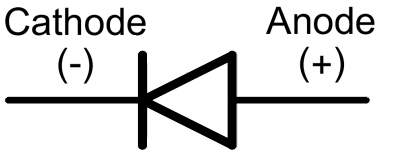
Current through a diode can only flow from the anode to the cathode, which would explain why it's important for a diode to be connected in the correct direction. Physically, every diode should have some sort of indication for either the anode or cathode pin. Usually the diode will have a line near the cathode pin, which matches the vertical line in the diode circuit symbol.
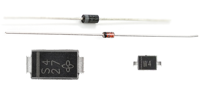
Below are a few examples of diodes. The top diode, a 1N4001 rectifier, has a grey ring near the cathode. Below that, a 1N4148 signal diode uses a black ring to mark the cathode. At the bottom are a couple surface mount diodes, each of which use a line to mark which pin is the cathode.
LEDs
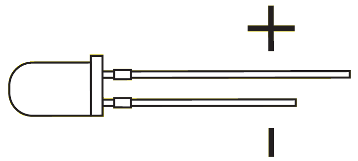
LED stands for light-emitting diode, which means that much like their diode cousins, they're polarized. There are a handful of identifiers for finding the positive and negative pins on an LED. You can try to find the longer leg, which should indicate the positive, anode pin.
Or, if someone's trimmed the legs, try finding the flat edge on the LED's outer casing. The pin nearest the flat edge will be the negative, cathode pin.
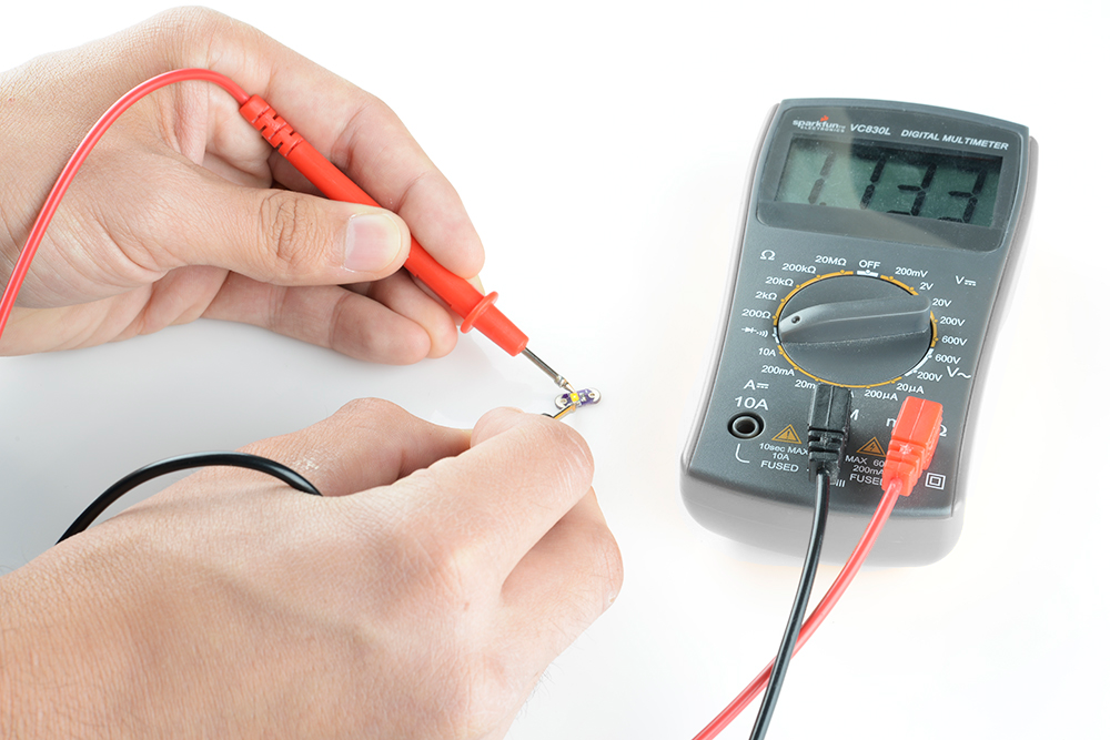
There might be other indicators as well. SMD diodes have a range of anode/cathode identifiers. Sometimes it's easiest to just use a multimeter to test for polarity. Turn the multimeter to the diode setting (usually indicated by a diode symbol), and touch each probe to one of the LED terminals. If the LED lights up, the positive probe is touching the anode, and the negative probe is touching the cathode. If it doesn't light up, try swapping the probes around.
Diodes certainly aren’t the only polarized component. There are tons of parts out there that won’t work if connected incorrectly. Next we’ll discuss some of the other common polarized components, beginning with integrated circuits.
Integrated Circuit Polarity
Integrated circuits (ICs) might have eight pins or eighty pins, and each pin on an IC has a unique function and position. It's very important to keep polarity straight with ICs. There's a good chance they'll smoke, melt, and be ruined if connected incorrectly.
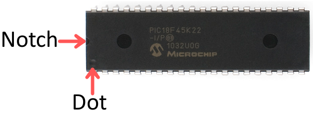
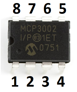
Through-hole ICs usually come in a dual-inline package (DIP) -- two rows of pins, each spaced by 0.1" wide enough to straddle the center of a breadboard. DIP ICs usually have a notch to indicate which of the many pins is the first. If not a notch, the IC might have an etched dot in the casing near pin 1.
For all IC packages, pin numbers increase sequentially as you move counter-clockwise away from pin 1.
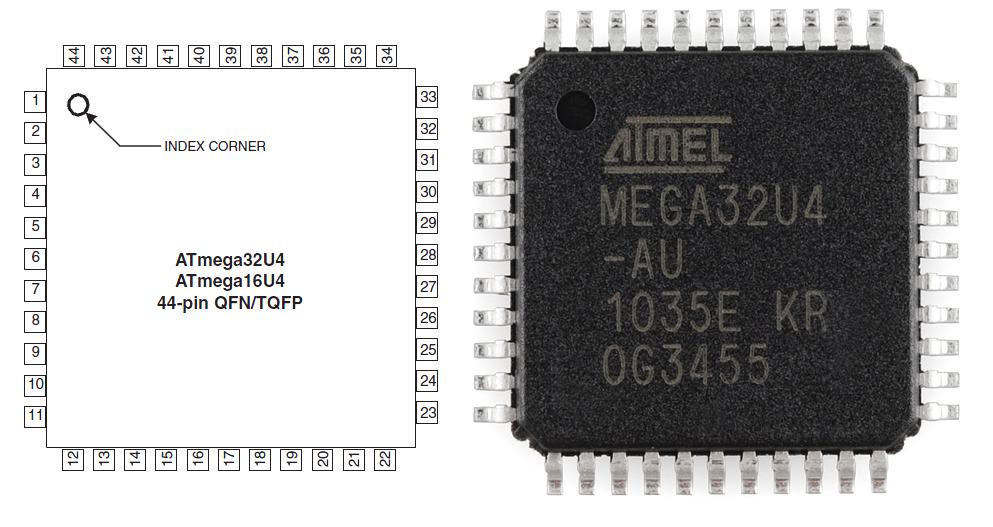
Surface-mount ICs might come in QFN, SOIC, SSOP, or a number of other form-factors. These ICs will usually have a dot near pin 1.
Electrolytic Capacitors
Not all capacitors are polarized, but when they are, it's very important not to mix their polarity up.
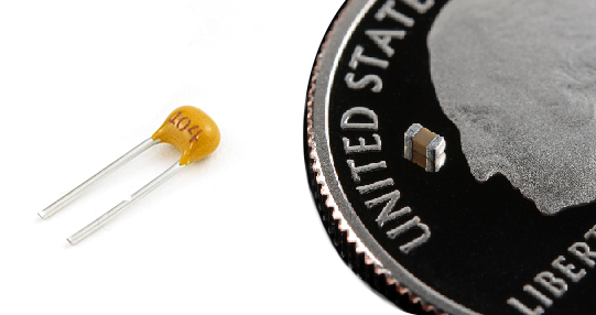
Ceramic capacitors -- the small (1µF and less), commonly yellow guys -- are not polarized. You can stick those in either way.
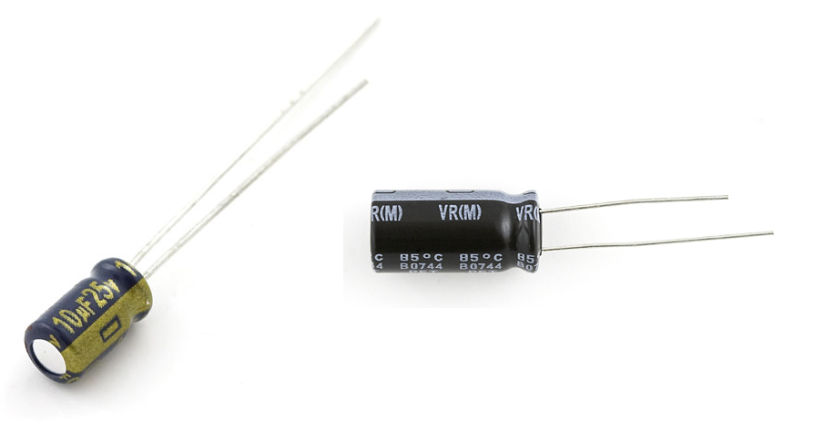
Electrolytic caps (they've got electrolytes), which look like little tin cans, are polarized. The negative pin of the cap is usually indicated by a "-" marking, and/or a colored strip along the can. They might also have a longer positive leg.
Below are 10µF (left) and a 1mF electrolytic capacitors, each of which has a dash symbol to mark the negative leg, as well as a longer positive leg.
Applying a negative voltage for an extended period to an electrolytic capacitor results in a briefly exciting, but catastrophic, failure. They'll make a pop, and the top of the cap will either swell or burst open. From then on the cap will be as good as dead, acting like a short circuit.
Other Polarized Components
Batteries and Power Supplies
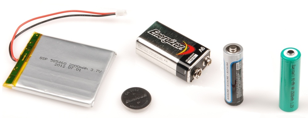
Getting polarity right in your circuit all starts and ends with getting the power supply connected correctly. Whether you're project's getting power from a wall-wart or a LiPo battery, it's critical to make sure you don't accidently connect them backwards and apply -9V or -4.2V to your project accidently.
Anyone that's ever replaced batteries knows how to find their polarity. Most batteries will indicate the positive and negative terminals with a "+" or "-" symbol. Other times it might be red wire for positive and a black wire for negative.
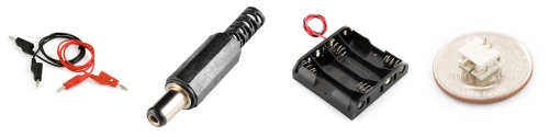
Power supplies usually have a standardized connector, which should usually have polarity itself. A barrel jack, for example, has two conductors: outer and inner; the inner/center conductor is usually the positive terminal. Other connectors, like a JST, are keyed so you just can't connect them backwards.
For extra protection against reversing power supply polarity, you can add reverse polarity protection using a diode, or a MOSFET.
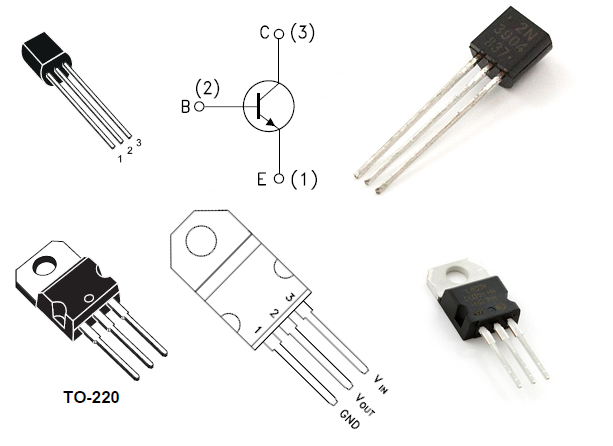
Transistors, MOSFETs, and Voltage Regulators
These (traditionally) three-terminal, polarized components are lumped together because they share similar package types. Through-hole transistors, MOSFETs, and voltage regulators commonly come in a TO-92 or TO-220 package, seen below. To find which pin is which, look for the flat edge on the TO-92 package or the metal heatsink on the TO-220, and match that up to the pin-out in the datasheet.
Etc.
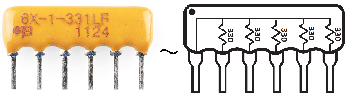
This is just the tip of the polarized-component iceberg. Even non-polarized components, like resistors, can come in polarized packages. A resistor pack -- a grouping of five-or-so pre-arranged resistors -- is one such example.
Fortunately, every polarized component should have some way to inform you which pin is which. Be sure to always read the datasheets, and check the case for dots or other markers.
Resources and Going Further
Now that you know what polarity is, and how to identify it, why not check out some of these related tutorials:
- Connector Basics - There are a number of connectors which have polarity of their own. Usually this is a great way to make sure you don't apply power or some other signal backwards.
- Diodes - Our shining example of component polarity. This tutorial goes further in-depth on how diodes work, and what types of diodes are out there.
- LilyPad Design Kit Experiment 1 - Circuits don't just exist on breadboards and circuit boards, you can sew them into shirts and other textiles too! Check out the LilyPad Design Kit tutorials to see how to get started. Knowing polarity will be huge in wiring up those LEDs correctly.
Interested in learning more foundational topics?
See our Engineering Essentials page for a full list of cornerstone topics surrounding electrical engineering.
